

This post will teach you how to program a Building Automation System. But not in the way you think…
Of all the topics I’ve discussed, this is the one I’ve skirted around the most. I’d been struggling with how to best teach this topic. Not because I don’t know how to program but rather because each company has a different set of programming tools. So therein lies the rub, how do you teach a topic that is unique to each vendor…
Well, after a ton of hemming and hawing (that’s a southern US phrase for y'all that means I was procrastinating…) I decided to ignore the vendor problem and just dive into the basics.
So without further delay...
The definitive guide to building automation programming
Table of Contents
OVERVIEW: what does this guide cover?
This guide is going to teach you the fundamentals of BAS programming. Even if you've been programming controls for several years you will still find some nuggets in this guide.
On the flip side, if you are in sales or management, this guide will help you understand what the "programmers" are doing when they disappear and hit your job for 80 hours of work...
So here's how this is going to go down.
We are going to start this off by discussing the fundamental concepts of inputs and outputs. From there we will look at the most common logic blocks and how they work. Then we will dive into several of the step-by-step processes that I use when I am programming.
A quick video tutorial
I was almost tempted to not put these videos here. My fear was that you would watch the videos and skip the rest of this guide. That would be a huge mistake as this guide covers so much valuable information.
So you have to promise me that you'll read the rest of the guide after watching these videos.
Programming Overview Part 1
Programming Overview Part 2
Block Programming Fundamentals
The basics
When it comes to programming a BAS there are a couple of core concepts you need to master.
Contrary to popular belief, you don’t need a “coding” background to program a BAS. What you need is a logical mind and an understanding of all the “variables”.
So what are variables?
As I see it there are three main variables when it comes to programming. These are:
Inputs and Outputs
Inputs and outputs, pretty simple right?
Yet, I can’t begin to tell you how many projects I’ve been on where I was asked to figure out what was wrong with a system only to realize that the inputs were misconfigured.
Misconfigured you say?
What does that mean?
Well, in the world of BAS, your inputs and outputs are nothing more than electronic components that receive and send digital or analog signals.
Take the 0 to 10-volt direct current (VDC) input. If I gave you a 0 to 10 VDC and told you to pull it into your control in order to control a valve could you?
Maybe…
Would it be effective?
Probably not…
The issue with inputs and outputs has to do with the context of the input and output.
You see a 0 to 2000 PPM CO2 sensor has a totally different range and scale than a 0 to 100% RH sensor.
Which brings us to the crux of the matter understanding range and scale.
I’d love to tell you that there is absolutely no math involved, but that simply isn’t true. The good news is we aren’t talking about Ph.D. level mathematics just some basic fractions, division, and multiplication (and by the way, it’s ok to use your calculator!)
So if I have a 0 to 100% RH sensor that puts out a 0 to 10-VDC signal. What do I know?
Well, let’s look at one and find out.
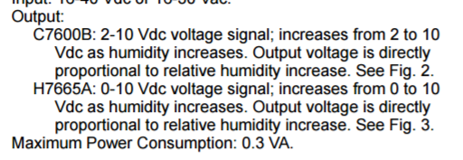
I grabbed some screenshots from a relative humidity sensor and, as you can see, this sensor has two potential options: A 2 to 10 VDC and a 0 to 10 VDC output.
For the sake of simplicity, we are going to look at the 0 to 10 VDC signal.
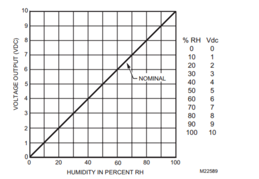
Take a look at the diagram above and you can see that it has a proportional scale. But wait, I'm assuming you know what a proportional scale is.
A proportional scale is quite simply a predictable output based on an input. In the graph above for each 1% of relative humidity is 0.1 VDC so 10% relative humidity would be 1 VDC.
So the proportional aspect of this scale means that for each specific increase in a value I should represent a set change in my BAS controller.
Now here is where things get interesting.
In some controllers, you will just edit the input and set the Input and output range manually. So for this example, you would set your range of 0 - 10 VDC to equate to 0 - 100%.
In some cases, you will have to define the scale. To do this you need to know the level of granularity you want. The easiest way to determine the scale is to divide the input range by the output range.
Scale = input Range / output Range
As I mentioned earlier, the scale of the humidity sensor would be (.1). So for each .1 increase in voltage, you increase relative humidity by 1%.
But what if your input or output isn’t proportional? Good question.
Many things in the BAS world are non-proportional for example a fan curve or a flow sensor or maybe a temperature sensor.
Fortunately, most of the non-proportional sensor types are preprogrammed into most of the modern controller inputs. But let’s say you don’t have the sensor type as an option in your controller.
This is where you need to use a custom range with multiple touch points.
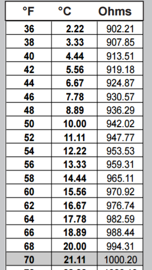
The image above is an RTD chart.
This chart is used to correlate the resistance to temperature. When you select a specific temperature sensor type you are telling your controller to use a predefined range of input to output relationships (in this case resistance to temperature).
If you have an input device that has a variable range to output relationship you will want to configure the range in the input.
Virtual variable and global variables
Next, we come to virtual points and global variables.
Virtual points are editable variables that may or may not come from the physical controller. For example, your zone temperature setpoint is a virtual variable. It does not physically exist as there is no "zone temperature setpoint" device.
However, since you need to modify the setpoint you will need to map it as a virtual variable.
In addition to this, you have global variables. These are points that come from other devices.
A good example of this would be an Outdoor air sensor. This sensor may exist on another controller. The data from this sensor is then shared globally, meaning to all controllers.
Set points (both hard-coded and adjustable)
I talked about setpoints earlier and we will definitely dive deeper into them as we progress through this article. Set points are the values that a process will control to.
What is a process?
A process is a step of actions that are used to maintain a process variable (temperature, pressure) at its set point.
A very common process is commanding a physical damper output open or shut based on a zone temperature setpoint.
The important thing to know about setpoints is that there are adjustable and non-adjustable setpoints.
An example of an adjustable setpoint would be a temperature setpoint. This setpoint could be adjusted by any user who has permission to access the setpoint.
The other type of setpoint is hard-coded setpoints. These are the setpoints that the program is depending on. Some folks will call these "Constants" or "hard-coded setpoints". The name doesn't matter as much as the function.
For example, I'm sure you've heard the screeching noise that a chiller makes when it short-cycles (short-cycling is when a mechanical system turns on and off too rapidly). Well in order to make sure this doesn't happen programmers will hard-code minimum run times into their programs.
These minimum times will make sure that the chiller runs for a set time before being able to turn off. As you would imagine you don't want folks just randomly changing these variables. That is why you use hard-coded setpoints.
Alright, with that out of the way it's time to move into the meat of this post. And that meat my friends is the topic of logic components.
Logic Components
If you dig into any BAS programming software you will begin to notice that all of the different software solutions pretty much use the same logic components.
But what is a logic component?
Well, before your BAS controller can command an output or read an input it needs to have something tell it to what to do. The way we (as BAS programmers) achieve this is through a concept known as logic blocks.
Essentially logic blocks are visual (blocks) of code or actual code that tells the controller what to do.
I've narrowed down the logic blocks to five main categories. These categories are:
Over the next couple sections I am going to describe what each of these logic categories is and the different subtypes that exist within them. But, before I go there, I want to take a brief second to talk about datatypes.
Data Types
Datatypes are exactly what they sound like. They are the types of data that you are dealing with.
There are literally dozens of different datatypes depending on the BAS software you are using. But really at the end of the day, it comes down to three different datatypes. These data types are:
Binary Data
Binary data is just as it sounds. It is binary meaning it has two positions. In the BAS world binary is a term that is often misused.
All you really need to know is that binary data consists of two states and these states typically represent a 0 value and a 1 value. In most cases, the FALSE or OFF state is equal to zero and the TRUE or ON state is equal to 1.
Analog Data
Compared to binary data, analog data has a lot more flexibility. Analog data can represent a variety of different numbers depending on the datatypes precision (I'll come back to that term in a second) and whether or not it is signed.
Ok, so I just used two key terms. Precision is the level of accuracy or granularity you can provide. For example, 3.1 is less precise than 3.14. This is because 3.14 defines the value more granularly.
Next, we have the term "signed". This is a real simple term to explain. When you say a value is negative or positive you are using a signed data type. It is important to know if the BAS supports signed data types (pretty much all do) prior to programming your controls.
Multi-State Data
Finally, there is multi-state data. Multi-state data is data that has multiple states.
Now I have used the term state before but I haven't defined it.
State is the condition of an object. At the end of the day, all of the values your BAS reads and writes come from physical memory that exists in the sensor, controller, or supervisory device.
And those values are what make up the state of an object.
For example, if I have a two-position wall-switch I have an object that has two states, on and off. When I change the position of that wall switch I am changing its state.
Well, in the BAS world there are devices and software objects that have multiple "states".
One of the most common stateful (meaning it has different states) objects is occupancy.
In most control systems you will have 4 states for occupancy. Those states are Occupied, Unoccupied, Standby, and Off. Inside your BAS programs, you will execute different snippets of code based on what state you are in.
Alright, now that we have those concepts under our belt let's take a look at the different kinds of logic we can encounter.
Boolean Logic
The first logic type we have is called boolean logic. Boolean logic comes from the world of binary and essentially it deals with True or False statements, also known as binary statements.
In the world of computers, you have the concept of a bit. A bit is a single piece of binary data.
A bit is either set to a 1 or a 0.
Often times in the BAS world a binary bit will be displayed using the terms true and false, with true equaling 1 and false equaling 0.
Ok enough about the computer side of things...
When it comes to boolean logic you have four main object types.
Here's the deal most half-way decent BAS support graphical programming. Now if the BAS you are using doesn't support graphical programming you will still take value from these descriptions it just may not be as valuable.
Graphical programming represents software code using graphical icons.
This allows you to avoid writing miscellaneous code so that you can focus on programming the BAS.
As I mentioned there are four object types. These object types are:
OR Gate
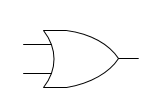
To give you an idea of how all this works lets look at the code underlying an OR gate. I promise this is the only time we are going to look at code.
An OR Gate works like this.
OR1(value1,value2, result) // Where the value1 and 2 are the inputs and the result is the output
 IF(Value1 = 1 || Value2 = 1)
 {
 result = 1; // 1 = true
 } else {
 result = 0; // 0 = false
 }
So what is happening in that little snippet of code I wrote. Essentially two input values are being put into a function. A function is a set of code that performs a specific purpose.
In the case of the OR gate, the purpose is to determine if one or both of the values are true. If they are true then the resulting output (called result) is passed a value of 1 which equals true. If none of the values are true then the code outputs a 0.
In order to know what the output of a gate should be we use a concept called the truth table. A truth table compares the inputs and shows you what the output should be.
Here is the truth table for an OR gate.
| Input 1 | Input 2 | Output |
| 0 | 0 | 0 |
| 1 | 0 | 1 |
| 0 | 1 | 1 |
| 1 | 1 | 1 |
Confusing? Yeah, maybe a bit. That's why we use graphical programming imagine trying to keep track of all of your objects and making sure they are being written to and read from properly!
AND Gate

Next up we have the AND gate.
Whereas the OR gate simply looks to see if any input is true, the and gate is only true (1) if all of the inputs are true.
Here is the truth table for an AND gate
| Input 1 | Input 2 | Output |
| 0 | 0 | 0 |
| 1 | 0 | 0 |
| 0 | 1 | 0 |
| 1 | 1 | 1 |
Pretty simple right?
XOR Gate
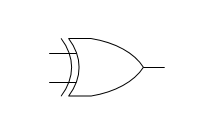
Now here is the confusing one.
The XOR gate, also known as the exclusive OR, basically is an OR gate and an AND gate with a not applied to the true side of the AND gate.
Now if that made your head spin a little bit don't worry you're not alone. I had this experience the first time I worked with a XOR.
The best way to learn a XOR is to look at the truth table.
| Input 1 | Input 2 | Output |
| 0 | 0 | 0 |
| 1 | 0 | 1 |
| 0 | 1 | 1 |
| 1 | 1 | 0 |
Essentially if you have a single input that is true (1), then the output is true. But at the high side of the gate (a double true) you actually have a false (0).
You would use this when you want to trigger some code based on a single condition like an alarm or command but you don't want to trigger it if both conditions are on.
NOT
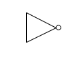
Now a Not gate is not a gate...
Seriously though, a Not object takes a binary value and flips it. So if you have a 1 you get a 0 and if you have a zero you get a 1.
You will often use NOT gates when you need to stop code from running.
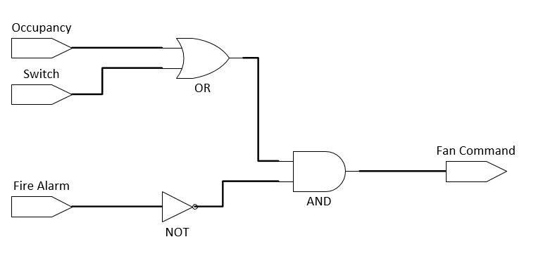
For example, take a look at this simple program below. It is designed to run a fan. The code will command the fan on if there is a manual push on the start button or the schedule is occupied as long as the fire alarm is not active.
Take a look at the code below and let me know if you can follow the sequence I described.
Comparative Logic

Comparative logic is just that. It compares two values and provides a binary output based on the logics result.
Now there is a concept we need to discuss before we discuss these objects.
And that concept is the deadband.
The deadband adds a buffer between the trigger point and the logic.
For example, I could say that my zone temperature (value 1) is greater than my zone temperature set point (value 2) with a 2-degree dead band (value 3). That means the logic blocks output will not turn true until my input is greater than the setpoint by 2-degrees or more.
This is very important!
If you do not have an adequate dead band then you will get a flappy logic block. This means that the block will be switching from true to false rapidly. I've seen folks try to work around this by adding timers after the block but that's like pushing the accelerator harder when your foot is on the gas.
So don't be stupid, add dead bands to your comparative logic blocks.
There are 4 main comparative blocks that we will look at. These blocks are:
Greater Than | Less Than
Greater than blocks simply compare two values to see if the 1st value is greater than the second value. The less than block simply looks to see if the 1st value is less than the second value.
You will often see these blocks being used for "mode switching". For example, you may say that cooling mode is enabled if the zone temperature (1st value) is greater than zone temperature setpoint (2nd value).
You will typically implement a deadband on these logic blocks so that the output doesn't cycle between true and false (remember these blocks produce a boolean true or false, aka 1 or 0 for their outputs.
Equal
Equal is quite simple. The output is true if value 1 and value 2 equal each other. The output is false if they don't.
Greater | Less Than or Equal To
The greater/less than or equal to blocks combine to concepts. The logic blocks will still produce a boolean true or false output. However, there are two conditions that can trigger the output. For example, with the greater or equal to block, the conditions to trigger a boolean true, are that value 1 is either greater than value 2 or equal to value 2.
Make sense?
Comparative logic blocks are some of the easiest logic blocks to understand.
Math Blocks
You can't escape math!
Seriously though, math blocks are very important for controls programming.
There are two main types of math blocks we will be working with and those are arithmetic blocks and span blocks. Let's dive in.
Arithmetic blocks
Addition, Subtraction, Multiplication, and division. These are the types of blocks that you will use in programming.
The most common areas that I see these blocks being used in are:
- Airflow calculation
- Valve position averaging
- K-factor calculations
Ok, onto the next "math" block.
Span block
The span block does exactly what its name entails, it spans a value. Humidity sucks, I grew up in Houston and being hot and wet was no fun! Fortunately, there are humidity sensors to help us measure the relative humidity so that we can dehumidify the space.
But there's a problem. Humidity sensors typically supply a 0 to 10-volt signal. Now you don't need to be a mathematician to know that 0 to 10 does not equal 0 to 100.
So how do we convert that 0 to 10 volt signal into a 0 to 100% RH signal? We use a span block.
The span block takes 4 inputs:
- Input Low
- Output Low
- Input High
- Output High
Fortunately for us most span blocks will automatically perform the calculation to determine the "step" meaning how much does the output increase each time the input increases.
Before we leave this category, let's have a look at a common calculation, valve position averaging. The purpose of valve position averaging is to provide an average valve position that will reset the chilled water setpoint on a chiller.
I used to think so what, won't the valves just close off and the pressure increase will make the secondary pumps slow down. After taking my Certified Energy Manager (CEM) course I realized that if I reset the chiller setpoint then I save even more energy by not producing the chilled water in the first place.
So what does this have to with valve position?
In order to do this "reset" we need to use some math blocks.
First off we need to average out our valve positions. There are two ways we can do this.
The first way is more complex and really I shouldn't be telling you this before you master the rest of what I'm teaching but what the hell, why not :-D.
Subroutines
This is an advanced example if it confuses you then just skip to the Sum and Divide method.
In most building automation systems you can actually gather all of the valve positions and put their values into an array of data (an array is simply an indexed storage area that keeps a set of values that you can recall by selecting their "index" in the array).
Once you have all of the values in the array you simply run a do while loop, meaning you keep running a loop of code while a condition is true. Essentially you would go through each value in the array, add it to a new value called total valve position.
Then you would go and take the count of valve values in the array and divide the total valve position by the number of valves. This would give you an average valve position.
Next, you would go and use a span block. Your settings would be:
- Input Low- 0% (Valve Position)
- Output Low- 52 deg (chilled water setpoint)
- Input High- 100% (Valve Position)
- Output High- 42 deg (chilled water setpoint)
Did you see what I did there? I reversed the span because as our valves open up we need to decrease our chilled water set point and as they close down we need to increase our chilled water set point.
The second way is not nearly as advanced but it takes a lot more work.
Sum and Divide
This method is ridiculously simple but time-consuming if you have a lot of valves.
You simply use a lot of addition blocks (most programming tools will support addition blocks with 8 inputs. You then consolidate the values from all of the blocks and divide the result by the number of valves.
The span block will not change you will still have the following settings:
- Input Low- 0% (Valve Position)
- Output Low- 52 deg (chilled water setpoint)
- Input High- 100% (Valve Position)
- Output High- 42 deg (chilled water setpoint)
The problem with this method is that if your valve count changes you may have to change a lot of blocks versus just adding another value to the array.
Flow Logic
Flow logic directs the flow of the program.
One way to tell if someone is new to programming is to check their code for a ton of Boolean Gates. If you see code that had AND, OR, and XOR gates all over the place you are most likely dealing with a new coder.
On small programs, this isn't a big deal but on large programs, this can start to impact the speed at which your program executes.
Plus every time you add another logic block you are adding another potential failure point and making your code harder to read.
That's why we have flow blocks.
Flow blocks will take the result of a set of logic and will trigger another set of logic.
Switches
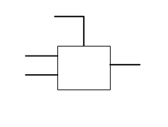
Switches are fairly simple objects.
A switch consists of 3 inputs:
- Trigger Input
- On Input
- Off Input
The trigger input excepts a boolean trigger (true or false). When the Trigger is true the switch will use the on input as the switches output. When the trigger is false the switch will use the off input as the switches output.
Pretty simple right?
Well, pay attention because the next block, the flip flop gate, will take this concept to an even deeper level.
Flip Flops
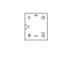
Flip flop gates tend to confuse new programmers. It doesn't have to be that way.
A flip-flop gate is nothing more than a software version of a latching relay. There are two settings on the flip-flop gate those settings are set and reset, just like a latching relay.
Flip-flop gates are usually used to latch alarms, or at least thats how I use them. When an alarm state is triggered, the flip-flop gate will latch into the set position passing through a specific "alarm mode" value. The only way the flip-flop gate will release from this "alarm mode" is if someone hits the alarm reset button (physical or software).
This is a great way to implement safeties like low-temperature or static pressure alarms in software.
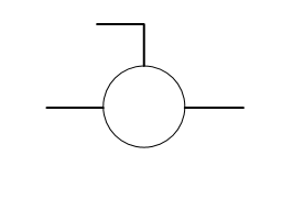
Mutliplexers (MUX) and Demuxers

If you've been programming for any amount of time you may have heard of the terms "mode" or "state". What this means is that based on some "factor" your program can be in a specific state.
Let's take a look at a very simple state, occupancy. Traditional occupancy programming calls for 4 different values (occupied, standby, unoccupied, and off).
In a traditional program, you will have a network input for your occupancy. This will be a multi-state variable (often known as an MV). Let's say that you have a PI loop (more on this later) that is controlling to zone temperature.
Do you want to have 4 different loops for four different setpoints?
Of course not.
Brief Rant: A good programmer should be able to accomplish his or her goal in as few lines of code as possible while maintaining the code in a streamlined fashion. You should strive to reduce complexity and make code easy to read. The reality is you will often not be the one troubleshooting your code!
So with that said, how can we change the setpoint for a single PID loop based on occupancy state?
We can use a multiplexer.
The multiplexer will have a control signal that will select which of the "inputs" it should pass through to its output. In the case of our scenario, we would map occupied, standby, unoccupied, and off set points to our multiplexer as inputs. The MV occupancy status would map to the multiplexer.
The multiplexer would then be set, via a table inside the multiplexer called a truth table, to pass the appropriate input through to the output.
This is a very common programming technique that you will use all the time.
Sequence Logic
Sequence logic sequences your logic.
I know, how's that for the phrase of the day! It seems basic but you'd be surprised how many folks don't sequence their logic. Don't worry though... outside of boolean logic, sequence logic is one of the easiest concepts to understand.
Sequencers
TBD
Timers
There are a ton of different timer blocks. Unfortunately, the amount and type of blocks vary by manufacturer. What does stay consistent are that timers allow you to interrupt the flow of a program.
Remember that BAS programs operate in cycles. The BAS program begins with an input and flows through a series of logic blocks until it triggers an output. After this is done the program cycles through again.
Back when I was programming Alerton controls you would literally number the blocks so that the program would know which blocks to execute. That works great in most cases, however, sometimes you do not want the logic to trigger right away.
An example of this would be a damper open status alarm.
When you are programming a controller to start a fan on a 100% outdoor air unit there are specific safeties you need to program into your controller code.
One of these safeties is the damper position safety. Because a 100% outdoor air unit only has one damper for air to enter the unit, you must make sure that damper is open prior to enabling the fan.
To do this I will map a negated (using a Not block) damper status and normal fan command to a AND gate. I will then place an on delay of 30 seconds after the AND gate. if after 30 seconds I have not received a damper status signal (meaning the damper is not open). Then I will trigger a flip-flop block which will trigger a damper not open alarm.
However, if I receive a damper status signal before the 30-second timer expires my output will not turn true and I will not trigger the damper not open alarm.
It is important for you to understand the difference of on and off delay timers as well as conditional single run timers. These objects are invaluable in your programming efforts.
Loop Logic
Here's something that a lot of folks don't know.
Controls programs are really just giant loops.
When you download your code to your controllers and supervisory devices you are providing a set of instructions for your devices.
Your devices have a processor inside them that will take this logic and will continue to run it again and again and again.
And that is why we have loop blocks.
Sometimes we need to hold a value and continue to adjust something based on previous conditions.
Think of a VAV box.
When a space is hot the box opens up and commands the damper actuator to continue opening the damper in order to let more cold air into the space.
Well, imagine if each time your controller ran through it's program it reset the actuator back to zero.
I mean think about it, how could an actuator go back to zero and drive open every second. That simply wouldn't work.
And that is why we have loop blocks.
Loop blocks retain their state each time the program runs. This means they retain the values from the previous loop and can use those values to make sure that the actuator stays open.
Alrighty, with that out of the way let's dive into loop blocks.
Proportional Blocks
Proportional blocks are ridiculously simple. Essentially these are span blocks with a different name. The key difference between a proportional block and a span block is the proportional block has additional settings like startup value.
This means that the block can start at 50% load.
This is a trick I've used in the past so I could have a single PID loop for cooling and heating (yes I know that's a bad idea but sometimes you need to be quick and dirty).
Essentially when the PID loop is controlling the setpoint it will sit at 50% output. This output will go into a span block that will take the 50% to 100% and make it 0% to 100% cooling output.
If the loop drops below setpoint then I will span the P output (50% to 0% output equals 0% to 100%). This will allow the loop output to control a heating element (SCR or a valve).
Proportional Integral Blocks
Proportional Integral blocks take the concept of a span block and a count block and put them together. Essentially what is going on is that each time the program runs (which in most BAS controllers is every second), if the set point is not being met the PI block will add or subtract the integral factor from output.
But what does this mean?
Well as we saw on the proportional block, the proportional component of the PI block will scale based on the difference from set point and the measured input (space temp, pressure, etc).
This works ok for some control modes, but what about things like pressure or temperature that can have huge swings in how they respond to changes?
This is where the integral factor comes into play. Integral, which is essentially a time-based component, will gradually increase itself the longer the PI block is not "on set point".
If you want to learn more about PI loops, check out my previous post on how PI loops work and how to tune PI loops.
The process
Ok, now that I've gone through all of the different "fundamentals" you now have the core skills to program a BAS controller. But how?
But how?
You see programming a BAS is a lot like a puzzle. As you saw in the earlier sections you have a ton of logic blocks available to you. Now here is where the real magic happens you need to be able to take the blocks and plug them in at the right spots.
So here's what we're going to do. I'm going to layout my approach to programming a BAS, along with several of the step-by-step processes I use.
You ready?
Good, here are the steps:
- Identify your inputs, outputs, and setpoints (as best you can)
- Configure your inputs, outputs, and setpoints
- Slice up your scope of work (sequence of operations) into modules/snippets
- Write your code
- Test your code
- Add any hard-coded setpoints
Step 1: Identify your inputs, outputs, and setpoints (as best you can)
So here you are, the first step and I know your excited to get programming. But we aren't going to program, not yet at least!
I know, I know, this is the ultimate guide to programming and the first step isn't to program. But, as some wise dude on the internet once said,
Failing to plan, is planning to fail
So let's make sure we plan.
And how we do that is by figuring out our inputs outputs and setpoints. But how?
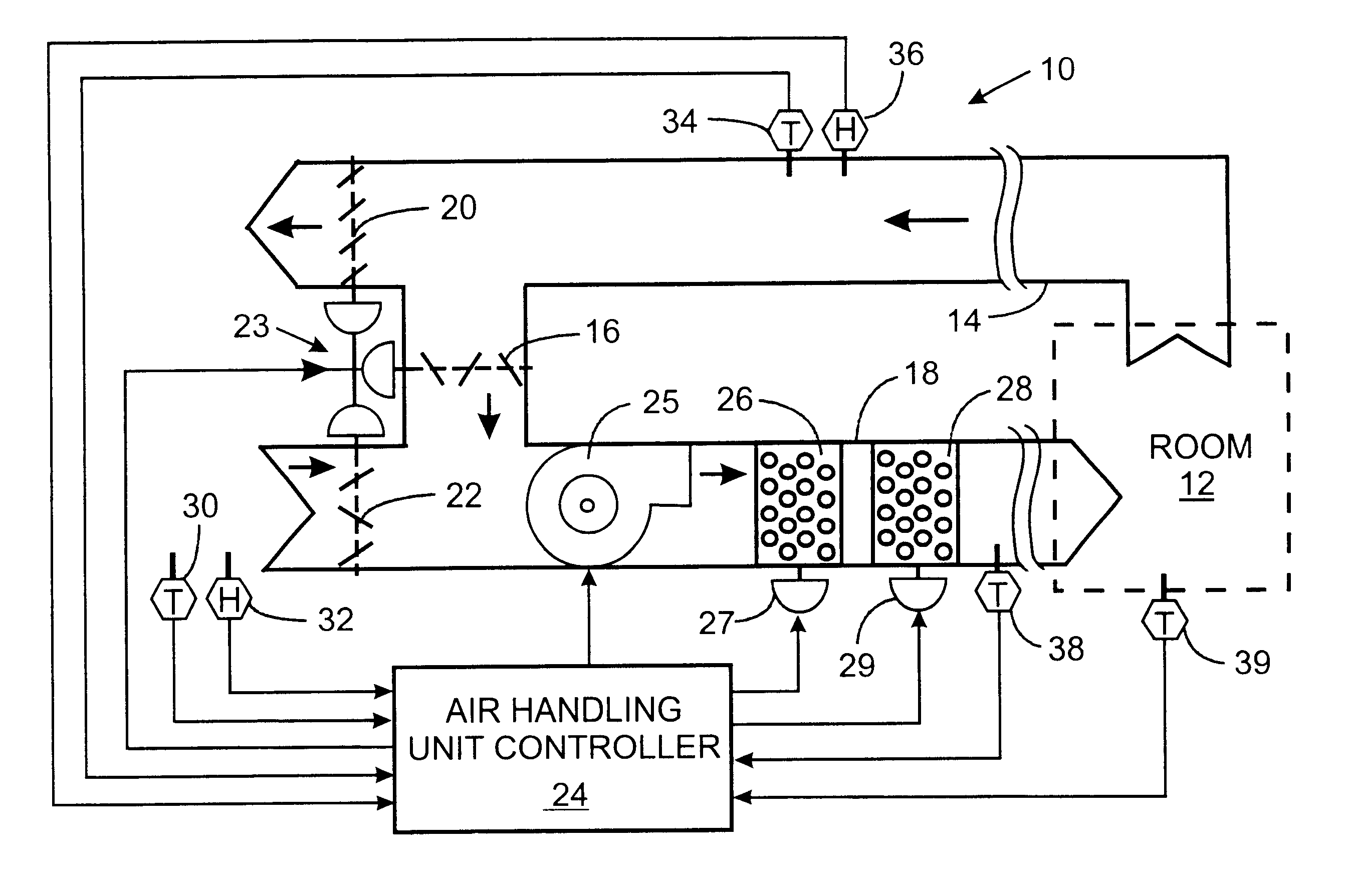
First, you need your sequence of operations and your controls drawing (or at least the mechanical layout of your HVAC equipment). In an ideal world, it should look something like this.
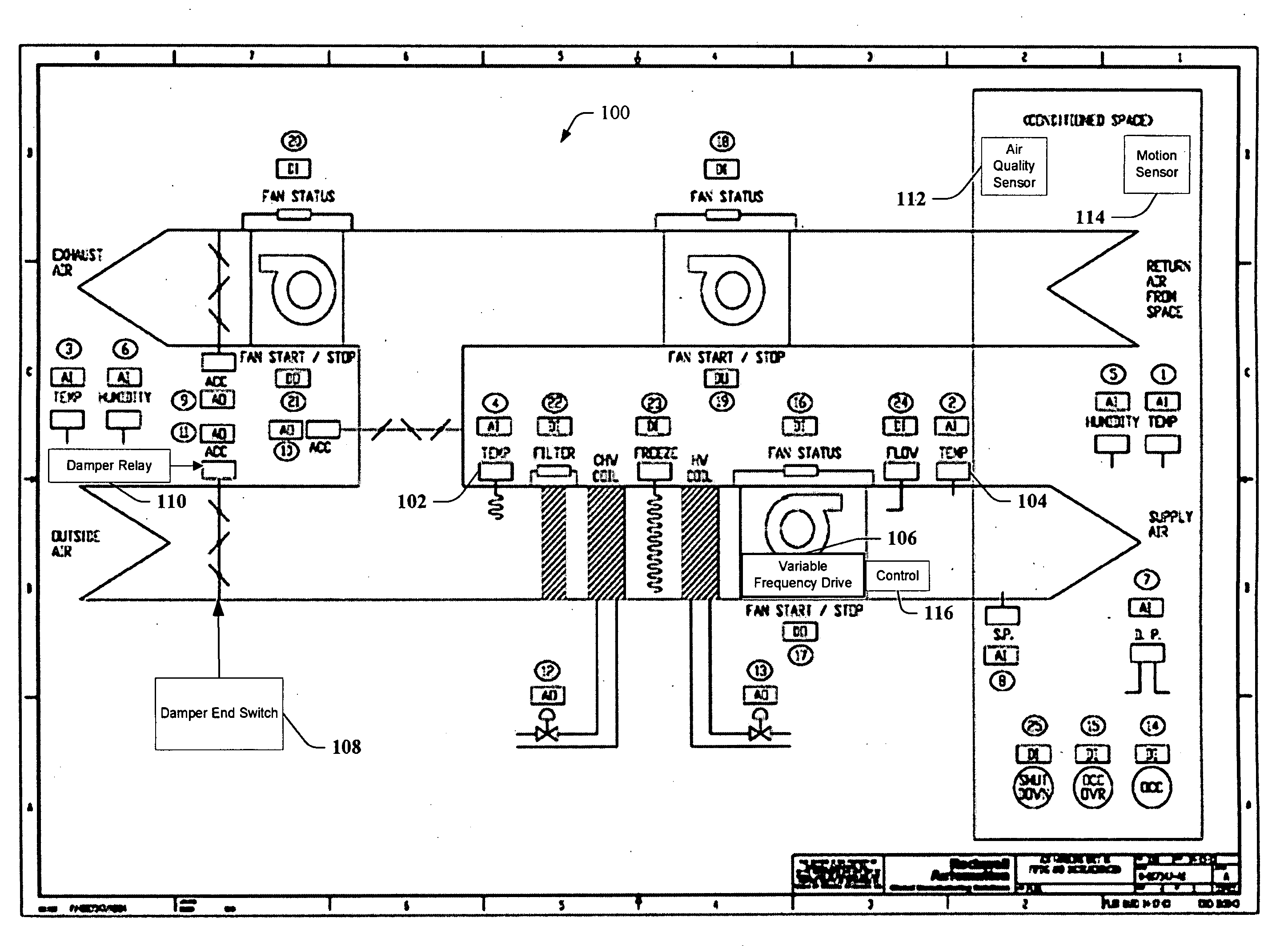
But in reality, it will most likely look like this.
So this is where the first epic failure or awesome success is made in your programming journey. You either take the time to work and create a detailed layout of the equipment that identifies the inputs and outputs.
Or you wing it and program based on a guess.
My personal suggestion to you is that you follow this 3 step process:
- Identify all controlled devices (outputs): Go through the drawing and identify all dampers (actuators), fans (VFD's or starters), and valves (actuators).
- Identify all sensed devices (inputs): Go through the drawing and identify all sensors (temperature, pressure, flow, etc), all safety devices (pressure switches, low temp alarms, fire alarms, etc), and all status devices (damper end switches, fan status switches, flow switches, etc).
- Using your head identify all setpoints (inputs): If you have to control it, then it probably requires a setpoint. Common ones are (discharge air temperature, mixed air temperature, static pressure, preheat, economizer, etc).
Step 2: Configure your inputs, outputs, and setpoints
Now that you have your inputs, outputs and setpoints it's time to lay them out. I'm laying them out according to the American Left to Right style, if you don't use that method, well, your SoL :-D
Setpoints and inputs go on the left and outputs go on the right.
Simple, that's it, next step!
Step 3: Slice up your scope of work (sequence of operations) into modules/snippets.
Engineers are awesome at engineering but they suck at sentence structure and spacing. I'm talking to you MEP designers and consulting engineers!
Stop writing 400 sentence sequences!!!! Look I get it, stuff needs to fit into the CSI format but come on, can you through in a paragraph every 4 sentences... please my eyes hurt!!!
Let's take a look at the cooling sequence below, I chose this one because it has some cool big words that no one outside the engineering world uses...
- Cooling Mode: When zone temperature rises above cooling setpoint (with 0.5ºF (adj) hysteresis), unit control shall be indexed to Cooling Mode and heating shall be disabled.
- First Stage – Cooling DAT reset: Cooling PID output from 1 to 20% (adj.) shall first reset DAT from Minimum 75F (adj.) to maximum of 55F (adj.) while supply air flow stays at minimum ventilation cfm / fan speed setpoint.
- Second stage – Increase Airflow: Upon continued zone temperature above setpoint Cooling PID output increasing from 21-100%), increase supply airflow setpoint from min to max heating cfm (or max cooling VFD speed (100% adj.)).
- Reverse shall occur as zone temperature drops below cooling setpoint, with hysteresis.
- [If OAT > RAT - 3, then revert unit control to minimum OA / Demand Based Ventilation Control. Designer Note: Apply only for units with economizer cooling only with no provisions for mechanical cooling]
So how the heck do we begin to digest this chunk of text...
Oh and, before we do that, hysteresis is a fancy way of saying differential, which in this case is the difference between the temperature sensor and temperature set point.
First off let's see what we can take from it. First off we can see that there are two cooling stages. Hmm, what logic blocks could we use if we have two stages... If you said sequencer, then you would be wrong.
Read closer young padawan. We are only using a single PID loop. See why this shit can be confusing?
A lot of folks will tell you that you need years of experience and mastery of HVAC systems to program controls. In some ways they are right, to be able to program extremely complex sequences or to figure out if sequences have "gaps or errors" you need experience.
But, with that being said, we still have to write code.
I've got a step-by-step process that helps me to digest sequences and write code. And the good news is you can do this even if you're just starting to learn HVAC.
The steps are:
- Identify the output
- List out the conditions
- Identify any other sequence tie-ins
Identify the output
In this case, we need to identify our outputs for this section of the sequence. You would think that since this is the cooling sequence our output is the cooling valve?
But wait what does this little snippet of sequence say?
Increase Airflow: Upon continued zone temperature above setpoint Cooling PID output increasing from 21-100%), increase supply airflow setpoint from min to max heating cfm (or max cooling VFD speed (100% adj.)).
So we need to increase our airflow set point as well?
To do that we would need to command our internal airflow setpoint.
Is there anything else?
[If OAT > RAT - 3, then revert unit control to minimum OA / Demand Based Ventilation Control. Designer Note: Apply only for units with economizer cooling only with no provisions for mechanical cooling]
Hmm, so does our unit have an economizer damper?
If you did step one you'd know the answer already. You did step one right?
So based on what we read, we have three major outputs:
- Cooling Valve output
- Airflow setpoint
- Economizer mode command
List out the conditions
So what are our conditions? Better yet, what is a condition?
A condition is a setting or event that dictates a response
So, how many conditions do we have in this sequence and what are they?
- Condition 1: When zone temperature rises above cooling setpoint (with 0.5ºF (adj) hysteresis)
- Condition 2: Cooling PID output from 1 to 20% (adj.) shall first reset DAT from Minimum 75F (adj.) to maximum of 55F (adj.) while supply air flow stays at minimum ventilation cfm / fan speed setpoint.
- Condition 3: Upon continued zone temperature above setpoint Cooling PID output increasing from 21-100%), increase supply airflow setpoint from min to max heating cfm (or max cooling VFD speed (100% adj.)).
There's one more condition do you know what it is?
If you said the reverse condition then you are correct. You will have to flip your conditions for shutting down the cooling.
Identify any other sequence tie-ins
As you read through the sequence did you notice anything that stood out to you?
More specifically were there any areas that seemed to tie to other systems? If so you will want to identify them.
The areas I saw were Heating Mode and Economizer Mode.
One area that was of particular interest to me was the occupancy mode. It is assumed that cooling will only run during occupied mode but will it? We need to clarify that.
We need to clarify that.
Step 4: Write your code
Ok, this is the part I can't do for you.
Each control system has a different programming environment. Some even have interfaces that allow you to select your configuration. You will need to understand how to use your systems programming tool.
I've included the majority of the logic blocks you will see but you may see a few other blocks depending on your programming tool.
When I approach writing code (if I don't have snippets of code already created) I like to write my code based on functional segments.
Here is how I write my code:
- Write out the inputs, outputs, and set points (which you should have already done)
- Break out the sequence into segments. For example on an AHU I would have:
- Occupancy Mode Control
- Fan Control
- Cooling Control
- Heating Control
- Damper Control
- Add in outside dependencies
- Connect all the logic
- Alarm and Safety Control
So why did I do it this way?
I like to layout all the conditions that could trigger occupancy and modes (cooling, heating, etc). Then I create the code for the individual control sequence sections. Finally, I add in the safety and alarm control
Then I create the code for the individual control sequence sections.
I grab any external data points, central plant status, building occupancy, outdoor air conditions, etc and I map them into the program.
Now I connect all the logic sections to one another.
Finally, I add in the safety and alarm control, I do this last because I don't want to miss any life safety or alarm conditions.
Step 5: Test your code
Test, test, test. There you have it.
Ok, a bit more than that. Testing is an art, but it can be broken down to a process.
You completed step 3 right? If so then you have your test plan.
You will grab the conditions that you listed out and those will be your test conditions. You will create the conditions by manually overriding your inputs.
So for the earlier example, we would first want to create a delta (differential) between the temperature sensor input and the setpoint of 0.5 degrees. This will invoke the first stage of the sequence.
Next, you will increase the delta again. This will cause the PI loop to react and you will see your PI loop's output increase past 20%. So what should happen now?
(DONT READ AHEAD UNTIL YOU ANSWERED THE QUESTION)
Ok, so you should have said that your airflow setting will increase. Did your program do that? If so, great!
Did your program do that? If so, great!
If so, great, if not, circle back, look at your code and make the edits.
Step 6: Add any hard-coded setpoints
Now that you've written and tested your code it's time to insert any final set points. Now, this is an area of debate among many BAS professionals.
Some folks will tell you that all set points and variables should be exposed externally. The argument is that by exposing all of these settings you will be able to adjust the program without "getting into the program".
Others will tell you that you should expose the bare minimum of set points and variables.
Based on my years of experience programming controls I tend to go with the later perspective. I like to expose the fewest points possible.
Here is the logic behind my perspective. I've written thousands of programs and I'm still not able to look at "settings" and know how a program works. If you are changing internal settings you should be in the program. Otherwise how will you know what effect your changes are having?
That is why the final step you should take is to hard code in your PID set points, timer setpoints, sequencer blocks, etc.
Basically, anything that isn't an environmental set point should be hard coded and not exposed to the user interface.
next steps
There you have it folks. While this guide will not make you an expert coder, it will expose you to all of the principles and processes related to writing BAS code.
With that, I want to be the first to welcome you to the world of BAS coding. There's a huge world out there and we've just started to touch on BAS coding concepts. There are things like global logic, sub-routines, and all sorts of code sequences that you can learn. If you're ready to learn more about BAS programming, I invite you to sign up for Smart Buildings Academy's free, intensive minicourse, Fundamentals of BAS Programming.

Do me a favor: What is the greatest tip you have for new BAS coders? And if you, yourself, are a new BAS coder, what else would you like to learn?
Scroll down to leave your response in the comments below.