
When I was a tech I realized there was not a good source of information on common protocols. That's why I created this guide. However, if you are in sales, facilities management, or engineering you will still find this guide to be helpful. This guide starts with general overviews and then dives deep into each protocol. Feel free to go as deep down the rabbit hole as you'd like.
[Author's Note] This guide will continue to be updated/restructured in a series of future releases, your feedback is critical to this.
So without further ado let's get started.
Table of Contents
What is a protocol?
A protocol is a set of rules that establishes how systems communicate. One of the best analogies for a
protocol is that of a language. If you think of the English language it has rules for the syntax and structure of language. It also has object types in the form of verbs, nouns, etc.
Protocols are the rules that dictate the structure, organization, and function of communication systems.
What are the major building automation protocols?
In the world of building automation there are three main protocols. Whenever I say this I get people emailing me, what about Dali, what about KNX, etc. Sure those are indeed protocols but when it comes to market share they are just a sliver of the market.
That's why when I focus on teaching protocols to new technicians or designers I think of the big three:
The rest of this guide will be spent extensively exploring these protocols.
Protocol #1: BACnet
Overview
BACnet Stands for Building Automation and Control Networks. BACnet was formed by ASHRAE in 1995 as Standard 135.
The current Addenda of BACnet is Addendum 135-2010aa links to all of the BACnet addendums can be accessed Here. We've also created a thorough guide to BACnet that you can read here.
BACNet is a communication protocol. This is not to be confused with Niagara which is a framework.
A Protocol is a set of rules that applies to the following:
• Signaling
• OSI layers- MAC/Physical
• Error Checking
• Flow Control
• Messaging (to include sequencing and message format)
• Presentation
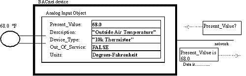
BACnet in its truest form was developed to provide a standardized approach to networks, messages, and data links. BACNet achieves this standardized approach by utilizing "objects".
BACnet Objects
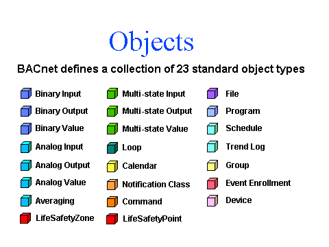
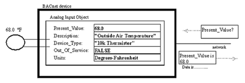
Objects are according to the BACnet standard " a collection of information related to a particular function that can be uniquely identified and accessed over a network in a standardized way"
• An object will provide a set of properties that contain data related to that object.
• BACnet has a set of 23 standard objects.
A deeper dive into objects, properties, and services can be accessed Here.
BACnet Device
A simple definition of a BACnet device is a collection of objects that represent the functions present in a real device. This is why virtual devices can be considered a BACnet device as well as physical controllers. The device is defined by the objects inside not its physical architecture.
BACnet LAN Types
BACnet currently supports five LAN types for communications
• BACnet over IP (Annex J)
• BACnet over Ethernet
• BACnet over Master Slave/Token Passing MS/TP
• BACnet over Point-to-Point (PTP)
• BACnet over ARCNET
BACnet consists of 5 data link and network layer protocol options types each with its own unique communication media. Of these LAN types the ones we will focus on are BACnet/IP and BACnet MS/TP.
Key Terms
1. Media - Media is a fancy way for saying the wire or "bus" that the device communicates on.
2. Protocol - A protocol is a set of rules for communicating
3. Router - A router is a device that routes messages to other devices.
4. Switch - A switch is a device that switches messages between devices.
5. Port - A port is a specific point from which a piece of media connects a device to another device.
With those definitions out-of-the-way we can now discuss communication.
How Does BACnet Communicate?
The two main forms of communication I will discuss are BACnet/IP and BACnet over MS/TP. Before I go into the specific media's we must realize that the BACnet message consists of a few key features. Authors note (while analyzing BACnet packets is outside of the scope of this article it is of such a high level of importance that I have included a link here)
The key features of BACnet messaging are:
- Object
- BIBB- BACnet Interoperability Building Blocks- These blocks allow you to build BACnet capabilities into a device. An example of this would be the "T" block which stands for trends and allows a device to have the ability to receive and communicate trend objects.
- BACnet services- These services are very similar to the "calls" a computer makes when connecting to a website for data. This allows the device to perform the same communication tasks as other devices.
- MAC Address- Media Access Control or MAC, is the method at which a device identifies itself on a specific media. For MS/TP this is typically done in the form of an 8 bit number for Ethernet this is typically a series of Hexadecimal numbers that device a devices Network Interface Card or NIC.
BACnet communicates via different methods utilizing the OSI network layer. The physical layer which consists of the wires and devices will allow the messages to be transported. Messages once transported will then be assigned a specific location to travel to on their local network in the data link layer.
Devices perform services calls for data and receive calls for data repeatedly. This is what causes the device to communicate. Now while the method from which the data is transmitted is different for IP over MS/TP the core services remain the same. A simplified view of this is shown below.
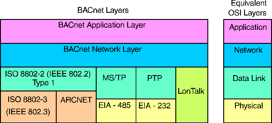
As you can see here there are 4 main layers in the BACnet stack that correspond with the 4 layers of the OSI model. The lower layers include the communication media and the communication protocols while the higher levels include the services and applications
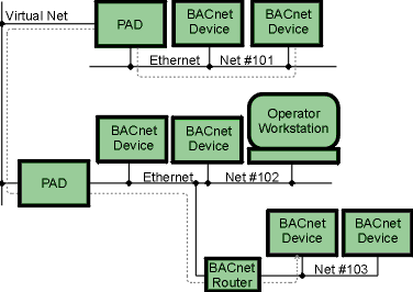
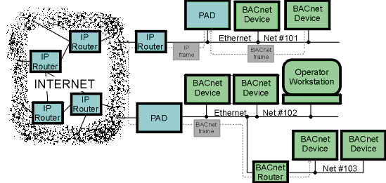
The two images above are examples of BACnet/IP transmission methods. We will get into the specifics of BACnet/IP later in the post but for the mean time you should be able to identify that there are BACnet devices communicating across Ethernet
BACnet/IP
BACnet over IP is a method from which BACnet/ Ethernet packets can use the framework of the UDP/IP protocol to send data to BACnet devices across multiple subnets. For those who are less IT savvy BACnet/IP allows messages that typically could only communicate on one network to communicate across multiple networks.
- UDP - User Datagram Protocol
- TCP - Transmission Control Protocol
- IP - Internet Protocol
- Subnet - A logical subdivision of an IP network.
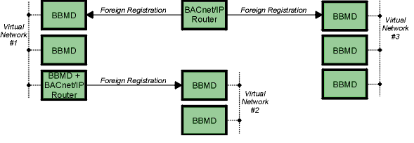
- BBMD - (BACnet Broadcast Management Device)- Allows the broadcast message "Who is/I am" to be transmitted across subnets.
- MAC Address - (Media Access Control)- This is a hardware identification for the device. In IP this MAC address is assigned a specific IP address.
- Static Address - This is an IP address that is set for a specific MAC address
- Dynamic Address - This is an IP address that is leased to a specific or series MAC address.
- Routing - This is the process of transmitting an IP message between different subnets.
What is TCP/IP and UDP/IP
TCP/IP and UDP/IP are protocols that allows messages to communicate across multiple Subnets.
IP:
- Allows for transmission of data
- Applies addresses to devices
- Allows for the creation of logical subnets
UDP:
- Connection-less protocol
- Allows for small packets that are non network intensive.
TCP:
- Verifies data transmission
- Has built in error correction
Why Do We Use BACnet/IP?
BACnet over Ethernet allowed building automation systems to transfer data via ethernet across a Bus architecture this worked well initially but with the advent of the internet and the desire to have a single control system across a network of buildings the need for networks larger then 254 nodes was needed. That is why ASHRAE adopted BACnet/IP in annex j of the 135- 1995 standard.
BACnet IP allows us to:
- Communicate across multiple subnets
- Create multi-campus control systems
- Utilize the benefits of fiber and giga-ethernet.
- Assign IP addresses to our BACnet devices making the web accessible.
How Does BACnet/IP Communicate?
BACnet/IP communicates using four methods.
- BACnet/IP to BACnet/IP (same subnet): In this situation the location of the two devices is already known by the host and the message is routed to the device using a local switch.
- BACnet/IP to BACnet/IP (different subnet): In this situation the location of the two devices is already known by the host and the message is routed to the device using switches and routers.
- Broadcast (same subnet): This is a standard Who is/ I am message sent across a local subnet for the BBMD to discover what the address are for the BACnet devices on the subnet.
- Broadcast (different subnet): This is a standard Who is/ I am message sent across a local subnet for the BBMD to discover what the address are for the BACnet devices on other subnets.
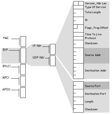
BACnet/IP uses a packet structure similar to a TCP/UDP Packet to pass messages from one device to another. A detailed description of a BACnet/IP packet is below.
Where is BACnet/IP Practical?
Not many vendors still use solely BACnet/Ethernet as most have adopted the BACnet/IP framework. Thus the ultimate answer is that BACnet/IP is practical for any solely BACnet system. The true choice on BACnet/IP is when you are utilizing a non native platform such as Tridium from which you have multiple protocol choices.
BACnet MS/TP
BACnet over MS/TP is a method from which BACnet MS/TP packets can use the Master Slave Token Passing (MS/TP) principle to transmit data across a bus network architecture (this will be discussed in further detail in my networking fundamentals posting). MS/TP messaging requires a physical medium (wire) and devices that have (Media Access Control) addresses. MS/TP communications use tokens to pass data. Only master devices can pass the token and only master devices can respond to the who-is request (this is why you cannot auto discover slave devices).
Key Terms
- Token- The Token passed by a MS/TP device to other devices. Token's can only pass on the local MS/TP network. Once a device holds the Token in can create and transmit application layer message
- MAC Address- This is an 8-bit number, which for master/slave devices is 0-127. This Mac address is used locally on the RS-485 link to physically address devices on the link, and is not passed through routers. It is comparable to the Modbus RTU slave address.
- RS-485- This is the standard physical medium associated with MS/TP. Typically, this is a 2 wire connection with a third wire for zero reference purposes.
- Baud Rate- This is the speed at which the MS/TP network communicates. General baud rates are 19200, 38400 and 76800. It is important to have all devices communicating at the same speed to avoid collisions and token drops.
- TRT- Token Rotation Time (TRT) is the time that the token takes to circulate every node on the network. TRT is updated at the supervisory device when it receives the token.
- RTT- Round Trip Time (RTT )is the time to complete one transaction of a BACnet confirmed Read Property service between the supervisory device and each field controller.
Network Ontology
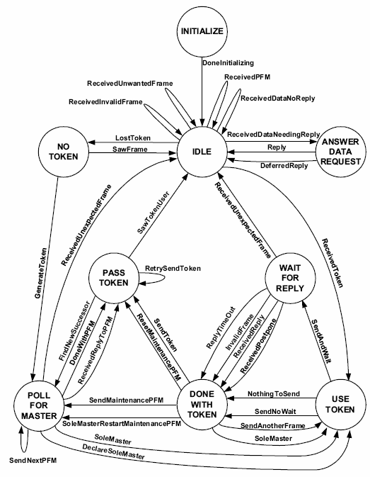
When a controller communicates on a BACnet MS/TP network, it first requests a token. Upon receiving a token, the controller is able to open a application layer message using a APDU. This allows the device to communicate to other controllers or the supervisory device. Only the device that has a token can communicate with other devices. A detailed description of this communication sequence is below.
Best Practices
There are three key best practices when you are designing and implementing a BACnet MS/TP control system:
- Ensure that the devices are set to communicate at the same baud rate. Do not simply rely on auto-baud, when possible manually set the baud rate. For shorter distance trunk runs use the 76.8k for LONger distance trunk runs use 38.4k.
- In order to keep the RTT and TRT times low, you should make sure that your controllers are addressed in sequence. This allows the token to pass quickly to each device in sequence rather then randomly moving throughout the network.
- The network instances should be arranged logically and in order. This facilitates effective troubleshooting and will allow the user to quickly find communication issues.
- Utilize the same wire media throughout the installation and do not ground both ends of a trunk bus (this creates an antennae effectively drawing interface to your bus).
Now we are going to dive a bit deeper into the BACnet stack.
BACnet Object Model
Objects are standard classes used by BACnet that have specific properties and services.
BACnet consists of 54 objects, although as you will soon see we only actually use a handful of these objects.
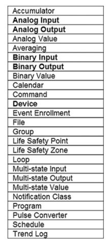
In a world full of objects…
Only a few objects reign supreme. The objects you should focus on are:
- Analog Input
- Analog Value
- Binary Output
- Calendar
- Device
- Multi-state Output
- Trend Log
- Analog Output
- Binary Input
- Binary Value
- Multi-state Input
- Multi-state Value
- Schedule
BACnet Properties
While BACnet doesn’t have “standard BACnet Properties”. There are three properties that always show up and those are:
- Object_Identifier
- Object_Name
- Object_Type
Outside of that each object has it’s own unique set of properties.
BACnet Services
Services are functions that can be requested and initiated by BACnet devices.
Service Initiation
Up to this point in the guide we’ve largely avoided the client-server dynamic in BACnet.
However, services are all about the client-server dynamic and understanding this will MASSIVELY improve your troubleshooting.
The client initiates a service and a server executes the service.
KEY POINT
The executor is responsible for the response data.
Two categories of services
There are two categories of services:
Unconfirmed Services - Unconfirmed services are fire and forget services. These services are NOT acknowledge.
Confirmed Services - Confirmed services are acknowledged by the receiving the service request. There are simple and complex acknowledgements
Complex vs Simple acknowledgements
Complex Acknowledgements - Complex acknowledgements provide confirmation of the service request aLONg with the requested data
Simple Acknowledgements - Simple acknowledgements provide confirmation of the service request without the requested data
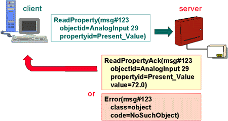
Common BACnet Services
There are several services we need to know in BACnet. Services are divided into service categories (note these are not all the categories):
- Alarm and Event
- Object Access
- Remote Device Management
Proctocol #2: LON
Overview
So what is the LON protocol?
LON is a protocol. It's a platform, it's framework. It's a lot of different things. And that is what confuses a lot of folks when they're first learning it. So in this overview, we're going to go through what LON is.
LON stands for Local Operating Network and it's essentially the common name for LONworks platform, which is developed by EcheLON
EcheLON came up with LONworks platform. And the LONworks platform itself consists of the LONtalk protocol. So yes, I know quite confusing, right? Well, here's the big difference between LON and other protocols. LON devices operate essentially in a peer to peer fashion on network, also known as the local operating network, hence the name LON. And where as a lot of the protocols require a supervisory device to process requests which then feeds data to either a server or another supervisory device LON is a little bit different.
In theory, you could stick all your LON devices onto a single network segment and when they're properly configured, they would communicate with one another. And that would be independent of any supervisory device that would also be independent of any server, independent of plugins, etc.
Now, with all that being said, let's discuss what the basic parts of the LON network are.
Nodes, Transceivers, and Channels
LON devices, which are known as nodes, and once again, it's really important to focus on the nomenclature because the nomenclature is often what confuses folks when you're on the phone with tech support when you're trying to figure out why stuff isn't working.
LON devices are known as nodes and they utilize network interfaces known as transceivers, these are similar to network interface cards. LON nodes communicate across the local physical network connection known as channels. So to summarize nodes use transceivers to communicate across channels. Now it's really important that each device on a specific channel must be communicating at the same speed.
FT-10 and EIA-852
This becomes really important when we're dealing with FT-10, and Eia-852. FT-10 is a two wire serial connection, and EI-852, is an IP connection. Now there's many other channel types with LON, but these are the most prevalent as with everything that we've learned, once again, nomenclature is very important. So pay attention to these names.
LONTalk Protocol
So the LONTalk protocol. As I stated earlier protocols are a set of rules for communications. LONTalk is different, but yet similar to the BACnet protocol.Both protocols use the concept of network IDs and source and destination IDs in communication
When it comes to LONTalk however there are actually two big differences between LONTalk and BACnet.
Channels
The first is that each device is communicating across a channel. And those devices can be independent of supervisory devices. Channels are the equivalent of field trunks in BACnet.
Network Variables
The other change is network variables, often called Network Variable Inputs (NVIs) and Network Variable Outputs NVOs. Basically, these are logical objects. They are logical objects that exist within the LON devices. And these logical objects allow the LON devices to essentially create logical bindings, aka logical links.
For example if you wanted to bind (that's what the act of connecting logical points in LON is called) global outdoor temperatures, you would bind the OAT from the controller with the OAT sensor as an NVO to an Outdoor Air NVI at all of the other controllers. This is very similar to a multicast method in BACnet.
LON Services
Now, what you will be happy about is that LON embraces unacknowledged and acknowledged message responses, so that's very similar to BACNet Confirmed and unconfirmed services.
The LON Stack
Now here is the biggie. BACnet uses a BACnet stack in order to communicate and the BACnet stack, essentially is how we go about implementing the BACnet protocol. The BACnet stack it requires each individual company to code their own BACnet stack the stack being from layer one of the OSI model (the physical layer) all the way to layer seven (the application layer). LON handles layers one through six inside the neuron chip. This ensures consistency across the physical layer to the presentation layer.
Now you may be asking yourself, ok Phil why does any of this matter?
First realize that everything except for the application is handled by the code in the neuron chips. This is really what brings the power to LON. It's what enables devices to be able to cross communicate and not have to worry about protocol mismatches, because the neuron chip has the same version of LON in it.
And what happens is that then the developers at these companies, they only need to create the program at the application layer. And that means they only need to create their plugins and programming interfaces which are application layer programs. The manufacturers will build upon this data from the neuron chip. But what is a neuron chip?
Neuron Chips
The neuron chip is a computer chip that has the LON stack preprogrammed inside it, manufacturers will then access the functionality of the LON stack from the chip using their application layer software.
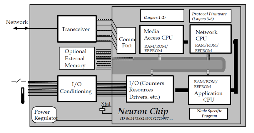
Neuron chips are where we get our physical addresses for our LON devices. Every neuron chip has a unique 48-bit ID. This ID known as the Neuron ID is what identifies nodes on the LON network.
When a node is added to the LON network you will press the service pin and the node will “wink” this is how you discover nodes that are added to the LON network.
Neuron id’s are the physical address. But nodes also have logical addresses.
Nodes are to LON what Devices are to BACnet.
Nodes exist to process inputs and drive outputs. Nodes also exist to share their data.
In the purest sense of LON there are two types of nodes:
- Sensor Nodes
- Actuator Nodes
Sensor Nodes
Sensor nodes “produce data” for the network. In their purest sense they should only be processing inputs and sharing this data across the network.
Examples of this would be LON light switches, LON door switches, LON temperature sensors, etc.
Sensor nodes share their data via NVO’s.
Actuator Nodes
Actuator nodes “consume data” on the network. In their purest sense they should only be driving outputs based on data from inputs on the network.
Examples of this would be LON light ballasts, LON door locks, LON damper actuators, etc.
Actuator nodes share their data via NVI’s.
Node Addressing
As we discussed, the LON node's physical address is the neuron ID.
But LON nodes also have a logical address. This address is known as node id and can be any number between 1 to 127. Node id’s however must be unique to their subnets.
LON Controllers
Let’s be realistic having a separate device for sensors and actuators, while cool in concept, is not very practical.
That is why some nodes are both sensor and actuator nodes. You will see this most commonly in LON Controllers.
There are two types of LON Controllers
- Application specific controllers
- Free programmable controllers
Application Specific Controllers
Application specific controllers (ASC) have a specific application or set of applications and are configured via the LNS OS using plugins. Plugins are manufacturer specific software that allow the configuration of LON ASC’s.
Free Programmable Controllers
Free programmable controllers (FPC) are controllers that have no existing application. The application is created dynamically using the manufacturer software.
The pros of FPC’s are that you can freely program them. The downside is that without the manufacturer software (which often is not shared) you have no way of configuring the FPC’s.
Which brings us to XIF’s…
XIF's aka LONMARK Device Interface’s
LONMARK device interface’s which somehow equals the acronym (XIF) is probably the most important file you’ll work with if you want to pull LON devices into your supervisory device.
XIF files tell your supervisory device what inputs, outputs, NVI’s, and NVO’s exist.
This is incredibly important as having no XIF or an incorrect XIF will keep your supervisory device from being able to communicate with LON nodes.
LON Objects
LON objects are similar to BACnet objects. They exist to perform specific outcomes and like BACnet objects LON objects can be nested inside other objects.
There are 6 Basic LON objects:
- Node Object
- Open loop sensor
- Closed loop sensor
- Open Loop Actuator
- Closed Loop Actuator
- Controller
Now there are multiple LON object types but the most important object types you will work with are:
- Network Variables
- Configuration Parameters
NV's and SNVT's
As we discussed earlier network variables are non-persistent objects that exist within nodes. You can create up to 62 NV’s per node.
NV’s are configured using SNVT’s.
Standard Network Variable Types know as (SNVT) define the properties of a NVI or NVO.
This is a very important concept. So much so we are going to spend some time looking through the LON SNVT table.
Configuration Parameters (CP)
Configuration Parameters (CP) are similar to NV’s in that they allow you to write to them. They are different in that they are persistent and you can have a unlimited amount of CP’s per node (based on node resources).
CP’s are configured using Standard Configuration Parameter Types (SCPT) are similar to SNVT’s.
Here is the difference between SNVT's and CP's
|
Capability |
NV |
CP |
|
Binding |
Yes, NVI to NVO |
No |
|
Count Limitation |
62 |
Limited by node memory |
|
Property Type |
SNVT |
SCPT |
|
Settings Saved |
Typically not |
Typically yes, into database |
Now at this point you may be wondering why all this CP, SNVT, NV stuff matters. It matter's because of this...
That is a LON Profile, a LON Profile is very similar to a BTL Application profile and it is how we go about "knowing" what we can and cannot integrate.
LON profiles exist to define:
- Mandatory NV’s
- Optional NV’s
- CP’s
Diving Deeper into the LON Network
Before we dive into databases and plugins (which are very important) we need to make sure we fully grasp what a LON network is.
Physical Network Structures
LON networks are made up of the following physical components
- Segments
- Nodes
- Repeaters
- Routers
Segments
A LON segment is a single physical network segment. Typically segments refer to FT-10 (the two-wire twisted pair version of LON). Segments consist of 64 (when using FTT (non-powered transcievers)) or less nodes and are typically limited to 900M.
Since LON is a free topology meaning you can do T-Taps and do not have to daisy chain devices the segment length can be difficult to calculate.
Repeaters
Repeaters serve the same function as BACnet repeaters. They exist to amplify existing signals. They can also allow you to add another 64 nodes to your subnet (notice I said subnet as subnet can have more than one physical segments).
Routers
Routers allow you to do four things:
- Switch transmission mediums
- Filter network traffic
- Isolate subnets into channels
- Refresh the network signal
There are two kinds of routers: Configured Routers and Learned Routers
Logical Network Structures
LON has physical and logical addresses.
The LON logical network structure has the following limits:
-
- Domains: 248
- Subnets: 255
- Nodes: 127
- Subnets: 255
- Domains: 248
There are two more logical constructs and those are channels and groups.
Domains
Domains are the equivalent of BACnet networks.
Domains can span entire campuses and contain multiple subnets as well as up to 32,385 nodes.
Domains are comprised of subnets and subnets are comprised of segments and Segments have nodes.
Subnets
Subnets are method of isolating LON segments.
Since LON is a purely peer to peer network structure with a free topology there needed to be a way to isolate and organize LON segments and nodes.
Enter the SUBNET!!!
The subnet can isolate all the nodes for a floor or even a small building!
Channels
Channels are segments. Actually channels are all the segments coming off a LON router..
Remember that thing called a repeater. It allows us to extend segments. Well. All those extended segments those are a channel.
Groups
Groups are a way of logically “grouping” nodes. A node can be a member in up to 15 groups and each group can have up to 64 nodes.
Groups exist at the domain level so this is a way to logically group up similar nodes across a LON domain.
The beauty of groups is that if you use similar nodes you can send a single message to a group instead of to each individual node.
Even better if you don’t require an acknowledgement you can have unlimited nodes in the group…
LON Network Services Operating System
The LON Network Services Operating System (LNS OS) is essentially a middle-ware layer that interacts with the LON network. So the LNS OS does a lot of different things.One of it's primary jobs is to interact with the LNS database in order to facilitate the transfer of LON network traffic.
So here's the deal. Earlier I said LON can operate without supervisory devices. Some of you may have been wondering how that works. In LON, all these devices just sit on the local channel (network) and they interact with one another.
But what if you want to pull data from the LON devices into graphics, a supervisory device, or simply edit them?
This is where the LNS OS comes in.
As I mentioned earlier the LNS OS acts as a middle-ware layer. A middle-ware layer is a layer between your application and the LON devices.
This layer enables your LON devices to interact with other software at the application layer. This is what allows you to do programming or to pull in the devices into a database. Ultimately the LON OS is what connects your devices to your applications.
LNS Database
The LNS database exists to store information on the LON Network Topology and device configuration. As you add and configure devices on the LNS the network layout, node addressing, and application configurations are stored in the LNS database.
The most important information that is stored is:
- Node Addresses
- Network Layouts
- Application Configurations
- NV Bindings
The LNS Server contains the LNS database. The LNS database actually consists of two databases. The global database and the network databases. Each LON network has it’s own network database.
The global database contains the network databases and the network databases contain the network and node configuration for their respective network.
In order for you to visualize and interact with the LNS you need a tool and that tool is the LNS server. The LNS server knows where nodes and devices are at based on the LNS database and allows clients to interact with the LNS.
You don’t have to have an LNS server but if you are a PURE LON installation then you will.
As mentioned the LON database stores critical information about the LON network. Other users can use the LON database to keep their LON network layout up to date.
If you go to a new site and you have no idea of how things are laid out you can simply upload a LON database backup and that will provide you all the information you need about the database.
Creating the LNS Database
The act of creating the LON Database is simple. You can utilize a variety of LON network creation software.
- The first step is to commission devices onto the network with either their commission plugin or the service pin
- Next, you configure the each one of the nodes
- Then, you add and configure your LNS server and/or any supervisory devices
- Finally, you create your backup of the LNS database
Occasionally you may have more than one person working on the LNS databse. You can either synchronize the database automatically or you can synchronize the database manually.
Ideally you want to try to avoid having two people commissioning nodes on the LNS database at the same time.
What if you show up on site and the LNS database is not there. To make matters worse no one knows where to find the database and the installing contractor has went out of business.
Most LON software has a capability called database recovery. You can use this capability to recover the database. This will recover the node address, application configuration, and NV bindings for any online device.
Working with the LNS OS and LNS Database
So whenever you're doing a LON integration or LON upgrade, what you have to realize is that the channels with the LON field controllers, those are all going to remain the same.
But here's the deal. LON Integrations can be tricky beasts, that is because there's an LNS OS, and there's an LNS database. And both of these need to be taken into account when you're going and working with an LNS network.
Because if you don't properly replicate that database, if you aren't cognizant of what has been set up on this kind of middle-ware layer, then if you go rip something out and you put something new in place you are really going to mess things up.
Not fully understanding this is has caused me to spend many days on job sites because of things I messed up in this process. So remember everything communicates through the LNS OS and the LNS Database dictates how everything is logically connected.
Programming LON
LON can be programmed one of two ways:
- Graphical free programming
- Plugins for application specific controllers (ASC).
Plugins are utilized to configure application specific controllers. You can get plugins from the manufacturer of the ASC.
Once downloaded you install the plugin and register it with your LNS building software. From there you can run the plugin and any configuration settings are stored in the LNS database.
Logical Comparisons BACnet and LONworks
To further drive home these concepts I've worked up a simple table.
| BACnet | LONWorks |
| BACnet Networks | LON Domains |
| Physical Segments | Channels |
| Nodes | Nodes |
| Objects | Objects |
| Property Types | SNVTS |
Protocol #3: MODBUS
Overview
Modbus is an industrial protocol that is largely used for power and conveyance monitoring. To save you and I some headaches we are going to define some terms before we dive into this protocol.
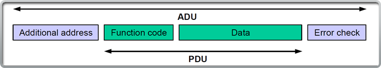
ADU- The application data unit (ADU) for Modbus, the ADU encompasses the PDU. The ADU handles error checking and “additional addresses for bulk messages.
PDU- The protocol data unit (PDU) for Modbus. The PDU is contained inside the ADU and handles the function code and data for Modbus ADU’s.
Function Code- The function code tells the Modbus server what data to provide in response to Modbus requests.
Ok with that out of the way let's dive in.
What is Modbus?
Modbus is a client-server protocol that functions primarily at the application layer.
Modbus clients submit requests to the Modbus server which responds to these requests. The server knows how to respond based on the function code in the PDU.
The server then responds to the client with an appropriate function code and any data if required. This is similar to how the BACnet Read and Write Property services function.
How Does Modbus Work?
As mentioned Modbus is a client-server application protocol. It works by transferring messages (ADU’s) between the client and server.
Messages are handled on a request-response basis.
There are two main physical layer protocol stacks that are used for Modbus:
- Modbus TCP- Utilizing TCP and IP
- Modbus RTU- Utilizing RS-485 or RS-232
What is the Modbus ADU and PDU?
The Modbus ADU is the “entire” Modbus message type. It contains four primary fields as seen in the image at the bottom of this slide.
The PDU is contained within the ADU and exists to communicate function codes and data for Modbus requests and responses.
How Modbus Messaging Functions
Modbus messaging is quite easy to understand once you get your head wrapped around the terminology.
Much like a webserver, Modbus clients request actions from the Modbus server. Here are the steps in Modbus messaging:
1.The Modbus client forms a ADU and PDU. The ADU contains additional addresses and error checking if needed as well as the PDU. The PDU contains the Function code and any data.
2.The server processes the ADU and generates its own ADU response with the appropriate function code and data contained in the PDU
But what about errors?
If the server experiences and error it will execute an exception response with the exception function code and exception code contained in the PDU.
Modbus PDU Types
There are three main PDU types:
Request PDU’s- These are issued by the client to request a “function” from a Modbus server.
Response PDU’s-These are issued by the server in a normal response to a client request.
Exception Response PDU’s- These are issued by the server if there is an exception (issue).
Modbus Object Basics
There are four types of Modbus Objects. Certain functions can be executed depending on the object type. The four object types are:
- Discrete Inputs – Single bit objects that only support read functionality
- Coils- Single bit objects that support read and write functionality
- Input Registers - 16 bit objects that only support read functionality
- Output Registers- 16 bit objects that support read and write functionality
Object addressing
Modbus supports two forms of addressing. The most common is the 0 to 65,535 range. There is also an extended range that goes beyond that range although it is not often used for BAS data. The table below describes the two ranges:
|
Object |
Standard Range |
Extended Range |
|
Coil |
00001-09999 |
000001-065535 |
|
Discrete Input |
10001-19999 |
100001-165535 |
|
Input Register |
30001-39999 |
300001-365535 |
|
Output Register |
40001-49999 |
400001-465535 |
These addresses are similar to object ID’s in BACnet
Discrete Inputs
Discrete inputs are single bit objects. They are also read only.
Being that they are a single bit these objects typically contain binary (digital) data.
Common examples are on/off or normal/alarm states.
Coils
Coils inputs are single bit objects. Coils support read and write functionality.
Being that they are a single bit these objects typically contain binary (digital) data.
Common examples are status states and binary commands (on/off).
Bit, byte, and bytes
Registers process 16 bits or two bytes worth of data this allows registers to support objects like temperature or an array of bits.
That’s why registers are used for reading analog values like temperature or writing values like % commands.
Input Registers
Input registers process inputs (what a surprise!). They consist of 16 bits and are read only.
A common use scenario for input registers is for read-only values like temperature or an array (list) of device status.
You have to read the entire register and pick the data from the bit(s) that is important for you. Most modern Modbus software will do this for you with minor configuration.
Output Registers
Output registers process inputs and outputs. They consist of 16 bits and support both read and write functionality.
Modbus Function Codes
Function codes are arguably the most important part of Modbus. If you understand function codes you can understand what the Modbus PDU’s are attempting to accomplish.
More importantly you can understand what errors are occurring on the network and why!
Deeper into Functions
There are three main function categories:
- Data Access
- Diagnostic
- Other
Function codes have a very specific range of numbers:
|
Function Category |
Range |
|
Public |
1 to 64 | 73 to 99 | 111 to 127 |
|
User Defined |
65 to 72 | 100 to 110 |
|
Reserved |
128 and above |
Data Access-Function Codes
Data Access Function codes are the most common function codes that you will work with.
Data Access breaks into three categories:
- Bit Access
- 16 bit access
- File record access
I’ve never seen a file record access function code actually being used in the field…
Data Access-Bit Access
Here are the most common bit access codes:
.
|
Object Type |
Function |
Function Code |
|
Discrete Input |
Read Discrete Input |
02 |
|
Coil |
Read Coil |
01 |
|
Coil |
Write Single Coil |
05 |
|
Coil |
Write Multiple Coils |
15 |
Data Access- 16 Bit Access
Here are the most common bit access codes:
|
Object Type |
Function |
Function Code |
|
Physical Input Register |
Read Input Register |
04 |
|
Physical Output Register |
Read Holding Register |
03 |
|
Physical Output Register |
Write Single Register |
06 |
|
Physical Output Register |
Write Multiple Registers |
16 |
|
Physical Output Register |
Read/ Write Multiple Registers |
23 |
|
Physical Output Register |
Mask Write Register |
22 |
|
Physical Output Register |
Read FIFO queue |
24 |
Diagnostic-Function Codes
Diagnostic function codes help you figure things out when stuff doesn’t work (and if you’re new to Modbus, trust me it won’t at times). There are no subcategories of Diagnostic function codes, however there are subcodes…
|
Function |
Function Code |
|
Read Exception Status |
07 |
|
Diagnostic |
08 |
|
Get Com Event Counter |
11 |
|
Get Com Event Log |
12 |
|
Report Server ID |
17 |
|
Read Device Identification |
43 |
Diagnostic-Diagnostic Sub Function Codes
Below is a list of the “sub function codes” for the diagnostic function. Note these are only for serial (Modbus RTU devices)
|
Sub Function |
Sub Function Code |
|
Return Query Data |
00 |
|
Restart Communications Option |
01 |
|
Return Diagnostic Register |
02 |
|
Change ASCII Input Delimiter |
03 |
|
Force Listen Only Mode |
04 |
|
Clear Counters and Diagnostic Register |
10 |
|
Return Bus Message Count |
11 |
|
Return Bus Communication Error Count |
12 |
|
Return Bus Exception Error Count |
13 |
|
Return Server Message Count |
14 |
|
Return Server No Response Count |
15 |
|
Return Server NAK Count |
16 |
|
Return Server Busy Count |
17 |
|
Return Bus Character Overrun Count |
18 |
Diagnostic-Read Device Function
The Read Device Function is extremely valuable and can help you identify what is on a Modbus network.
A Modbus device is required to provide:
- Vendor Name
- Product Code
- Major/Minor Revision
Out of these three data points, Vendor Name and Product Code are the most important.
Exception Codes and Error Handling
Modbus servers have four different “events” that are used for responding to client requests:
1.If no error occurs then the server responds according to the function code in the request
2.If the server does not receive the request it is the responsibility of the client to manage the timeout (error) due to a lack of response
3.If the server detects an issue related to the communication (CRC, bit parity, etc) No response is sent and the client must manage the timeout (error) due to a lack of response
4.If the server receives a malformed or mishandled request the server responds with an exception request
KEY POINT: SERVERS GENERATE EXCEPTIONS ON MISHANDLED REQUESTS NOT COMMUNICATION ISSUES!
Exception Codes
There are 9 exception codes that are commonly used. You can see them listed below:
|
Exception Code |
Name |
|
01 |
ILLEGAL FUNCTION |
|
02 |
ILLEGAL DATA ADDRESS |
|
03 |
ILLEGAL DATA VALUE |
|
04 |
SERVER DEVICE FAILURE |
|
05 |
ACKNOWLEDGE |
|
06 |
SERVER DEVICE BUSY |
|
08 |
MEMORY PARITY ERROR |
|
0A |
GATEWAY PATH UNAVAILABLE |
|
0B |
GATEWAY TARGET DEVICE FAILED TO RESPOND |
Modbus TCP
Device Addressing
Modbus devices have two addressing schemes:
- Addressing for IP devices
- Addressing for serial devices
Modbus Device IP Addressing
Modbus/TCP uses IP addresses for the device address. There is no limitation on how you address your devices if they are all IP.
If you have a serial network connected to a IP Address then you must keep that IP address the same otherwise the routing of Modbus messages to serial devices will be interrupted.
Since Modbus/TCP DOES NOT follow the master-slave topology of Modbus/RTU you are not limited to having a single “master” device. You can actually have multiple Modbus Server devices that can communicate to one another.
Server devices can also support client functionality.
The MBAP Header
The Modbus Application Protocol Header is a field that is unique to the Modbus/TCP ADU.
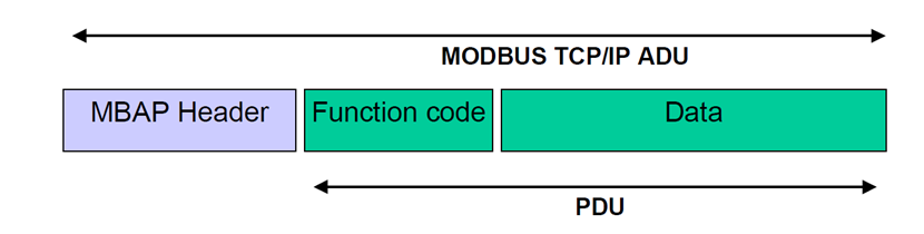
The purpose of the MBAP is to:
- Maintain the length of Modbus messages
- Identify slave devices
- Identify the Modbus transaction
Transmission Control Protocol (TCP)
TCP is a reliable protocol. This means that it creates a connection between two devices prior to sending information. These connections are called sockets.
We have to be aware of the port that is being used since Modbus/TCP is utilizing TCP at the transport protocol.
By default Modbus/TCP utilizes port 502.
The socket is initialized by something called the TCP handshake.
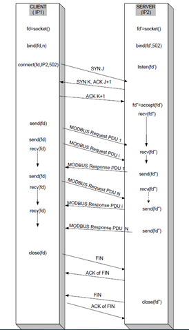
The TCP Handshake utilizes a series of actions to connect two Modbus devices together.
These actions create a connection. This connection stays open until communication is complete at which time the connection is closed.
MODBUS RTU
Modbus RTU Addressing
Modbus/RTU addressing is very similar to BACnet MS/TP addressing with the following caveats:
- Address 0 is the broadcast address
- There is only one master and it can be any address (although 1 is the normal choice)
- The address range is 1 to 247
Modbus RTU Standards
Modbus/RTU introduces several concepts.
For one RTU is not the only communication standard, there is actually Modbus ASCII as well (however in the BAS world we almost exclusively use RTU).
Focusing on Modbus/RTU there are 5 categories we will explore:
- Wiring Requirements
- Device limitations
- Speed
- Repeaters
- End of Line
Wiring
Modbus RTU wiring using 26 AWG at 9600 Baud is limited to 1000M.
Modbus/RTU is typically installed using the RS-485 standard and as such is typically limited to 32 devices on a single segment. Theoretically Modbus/RTU can support 247 devices with the appropriate amount of repeaters.
This is not typical. What is typical is a 32 or 64 device run.
Device limitations
Modbus/RTU is limited by the RS-485 or RS-232 device limits.
Since most BAS installations utilize RS-485 we will focus on that.
RS-485 standards limit Modbus to 32 devices at 3000ft (1000M).
Speed
Modbus/RTU is a slow network. It typically has communication times of 1 to 3 seconds per object poll (and this is with a 32 device network…).
Technically Modbus can support the same baud rates as BACnet MS/TP. Although Modbus/RTU is normally 9600 baud and occasionally 19.2k baud.
Repeaters
Repeaters allow you to extend the length AND capacity of Modbus segments.
We use repeaters to amplify the segments voltage as voltage drop is our primary concern on LONg or congested segments.
End of Line
End-of-Line termination is the same as BACnet MS/TP.
Consisting of (2) 120 ohm resistors (one at the end of each network run).
Master/Slave
Modbus/RTU uses the master/slave methodology but not like BACnet MS/TP.
Modbus/RTU consists of a single master device that communicates to all slave devices. It is this Master that will gather data from the slaves.
Typically the master device will be a protocol gateway converting Modbus to another network level protocol.
As I mentioned Modbus/RTU can only have one master and can have several slaves (up to 247) on a serial bus.
Master devices communicate using unicast and broadcast messages.
- Unicast messages are direct messages between the master and slave device. With the master requesting and the slave replying
- Broadcast messages are messages sent by the master to all devices on the serial bus. The clients do not reply to these messages.
The Modbus RTU PDU
The Modbus RTU PDU is similar to the Modbus TCP PDU
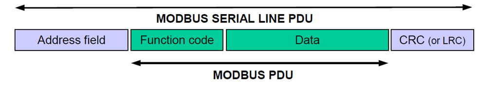
The only thing I want to point out here is the use of Cyclical Redundancy Checking (CRC). This is a concept used in network communications that checks for distortion in signals.
Configuration Settings
This is where most folks mess up Modbus/RTU.
Modbus RTU has some specific settings that must be used in order for “it” to “work”. These are:
- Baud rate: (typically 9,600 or 19,200 baud)
- Number of data bits: (typically 8 bit-binary)
- Number of stop bits: (typically 1 bit)
- Parity: (typically even or 0)
- Flow Control: (none or rts/cst)
What are some new protocols that are gaining traction?
Coming Soon...