

Several years ago I started writing a series about central cooling plants. As I've advanced in my building automation system (BAS) career, I've realized that central cooling plants are one of the most complex systems that a BAS technician will work on.
That's why I've taken these past articles and combined them to provide a primer on central cooling plants. In this post I will teach you about the three main topics related to central cooling plants and those are:
- An overview of central cooling plants
- Condensing systems
- Pumping systems
I look forward to your feedback.
Table of Contents
Central cooling plant overview
The central cooling plant is the life blood of an HVAC system. This series will begin to give the reader an understanding of what central cooling plants are and will act as a springboard from which we can launch into deep control discussions.
Key Terms
- Chiller- A mechanical device that takes the heat (measured in British Thermal Units, BTU's) from one medium (water, refrigerant) and transfers it to another medium (water, air, refrigerant).
- Pumps- Mechanical devices that move water throughout a piping system using fins and suction mechanisms.
- Cooling Tower- A mechanical device that takes the heat (also measured in BTU's) out of a medium and transfers it to the atmosphere.
- Piping- Tubing (Metal or Plastic) used to transfer water from a chiller to secondary device.
- Heat Exchanger or Plate Heat Exchanger- Transfers cooling from a Primary Source (chiller) to a secondary source (floor or building loop). Is often used to avoid pressure issues.
- Variable Frequency or Speed Drive (VSD) or (VFD)- Utilized to vary the speed or frequency of a pump, chiller, or tower motor.
- Mixing Valve- Utilized to Mix water from a primary loop into a secondary loop (more on this in advanced theory).
- Heat Trace- Electrical lining on externally exposed pipes to prevent the freezing of water.
Chiller types
Air Cooled Chillers
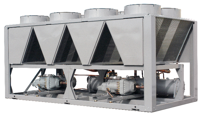
Air cooled chillers rely on air to absorb heat from the cooling medium inside the chiller. Typically an air-cooled chiller utilizes refrigerant that runs through a series of condenser coil banks with vertical exhaust fans. These fans draw air through the coil transferring heat from the refrigerant to the atmosphere.
The refrigerant then returns to the evaporator coil in which it absorbs the heat from the chilled water. This process follows the refrigeration cycle which will be explained in detail later in this article.
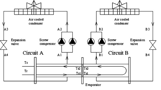
Air cooled chillers come with or without variable speed compressors and evaporator fans. Typically, air cooled chillers are used for partial load conditions that do not meet the minimum tonnage requirements of a water cooled chiller.
Water Cooled Chillers
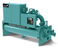
Much like air cooled chillers. Water cooled chillers rely on a medium to absorb heat from the chilled water that is returning from the building. In the case of the water cooled chiller, the medium is water.
Water has a greater BTU capacity and transfer rate than air. This means that you can transfer more heat out of the building with water than air. If you are feeling frisky and want to know more about BTU transfer ratios you can read in detail about them here.
Since water cooled chillers use water to exhaust the heat from their cooling medium, we need another device to exhaust the heat.
While most air cooled chillers have condenser sections built into the chiller, the water cooled chiller requires a cooling tower or heat exchanger to transfer heat from the water cooled chiller to the outside environment. Water is used to absorb heat from the chiller and then is transferred to a cooling tower that uses a process called evaporation to remove BTU's (heat) from the water.
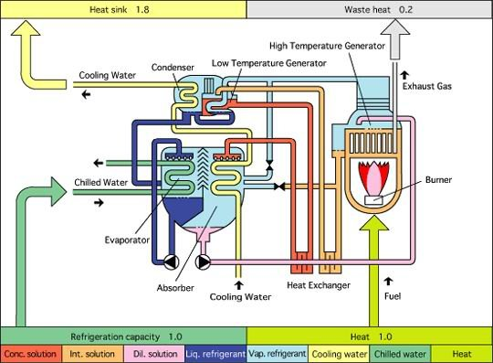
Absorption Chillers
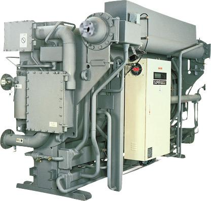
While similar to water-cooled chillers with electrical compressors, an absorption chiller relies on a chemical mixture to provide cooling. By utilizing gas or steam, an absorption chiller can have a thermal compressor that absorbs heat from the water and transfers that heat to process water.
While the real mechanics of how this works are beyond the scope of this article, it is safe to say that the same principles of transferring heat from returning chilled water to entering condenser water, still exists.
Cautionary note: Because water-cooled chillers produce a significant amount of heat, you must increase the GPM's (gallons per minute) of condenser water to compensate for absorbing the extra heat. Because of this, sequences must be considerate of the GPM demands on the condenser side for both water cooled and absorption cooled chillers.
Secondary devices
Cooling towers
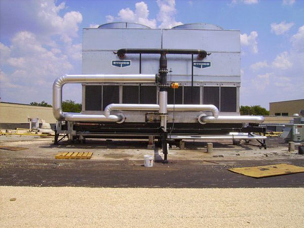
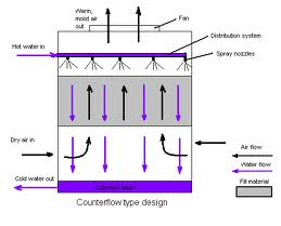
Cooling towers utilize the evaporative process to remove heat from the chillers condenser water. There is not much to say about cooling towers. They are relatively simple to control.
I will go into greater detail in a later post discussing control strategies, common sumps, and freeze protection among other things. I've posted a basic schematic of how a cooling tower works below.
Heat Exchangers
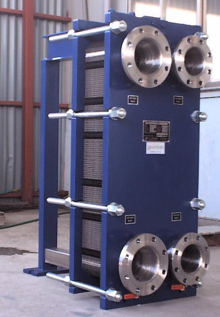
Plate heat exchangers allow engineers to design a system that can transfer chilled water across large areas and up multi-story buildings without having to compensate for the pressure gain of large vertical piping runs. Additionally, plate heat exchangers allow engineers to design a system that can provide free cooling from a cooling tower or outside source to a primary cooling loop.
Pumps
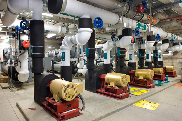
Pumps and piping are the heart and blood vessels of a chilled water supply system. Without proper pumping and piping, water will not be delivered in the right quantities or may not be delivered at all.
There are two types of piping for pumps:
- Parallel
- Series
How pumps are connected to the piping infrastructure, greatly impacts how you sequence your chillers.
A series system has devices that are in series or (one after another).
A parallel system, when properly implemented, can be run independently of another chiller as it exists as a separate circuit. I will talk more about pumping later in this article.
Basic design theory
The refrigeration cycle
If you were to ask me, "Phil what is the one thing I NEED TO KNOW for a career in the HVAC and BAS controls industry," I would say, hands down, it is the refrigeration cycle.
The refrigeration cycle is CENTRAL to everything we do in our industry.
When you fully understand the principles behind taking heat from one source and transferring it to another, not only will you understand how your cooling equipment works but you will also understand how heating works.
Ultimately, the HVAC industry is a numbers game. We keep heat from transferring in and out of the building using certain materials and pressure methods and we add or subtract heat using certain mechanical methods.
The key method is the refrigeration cycle, and ultimately the heat-transfer cycle.
So what is it?
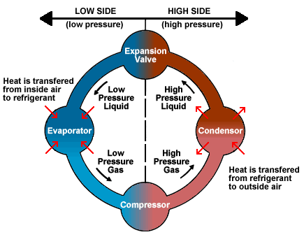
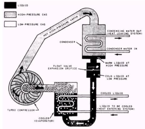
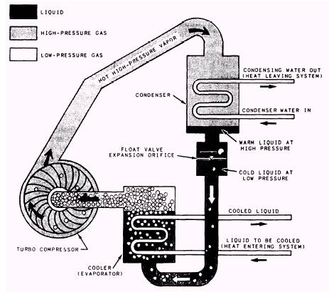
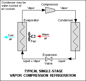
As you can see from the layout above, the refrigeration cycle is a method that is used to absorb heat from one medium that is typically air or water and then transfer it using refrigerant to another medium, either air or water.
Since refrigerant has different properties than water, it is able to perform state/phase changes at different temperatures and in different capacities.
First, refrigerant runs through the evaporator coil. The name of the evaporator coil is quite self-explanatory, as the refrigerant evaporates into changes state into a gas as it absorbs the heat from the medium.
Next, the refrigerant then passes through a compressor which, guess what, compresses the refrigerant back into a high-pressure gas form. The refrigerant now moves to the condenser coil and is now condensed back to liquid form as the outside medium absorbs the heat from the refrigerant. The refrigerant then passes through the expansion valve and onto the evaporator coil where the process happens again.
If you can understand this process, you will understand how chillers work. The whole chiller system and its secondary systems are all part of one giant refrigeration cycle. I know this a little bit of a stretch, as there are some aspects of water that do not function like refrigerant, but the premise remains the same.
Now as I mentioned all of these systems run through a series of piping and this piping is fed by pumping systems. So naturally it makes sense for us to turn our conversation to pumps.
And guess what?
The next section of this article happens to be about just that.
Pumping Systems 101
Key Terms
The following are some key terms that you need to understand as we move into pump theory and design:
- Open Loop System- An open loop system is exposed to the atmosphere. An example of an open loop system is a condenser water loop with an open tower.
- Closed Loop System- A closed loop system is isolated from the atmosphere and should have no external or internal leakage of water or air.
- Pump Curve- The pump curve shows the operating conditions for a pump in specific design conditions. This is the single most important chart for you to understand in pump design. Selecting the correct pump will allow you to meet your design conditions while operating at peak efficiency. We will cover pump curves in greater detail later in this article.
- Suction Head- The suction head is the sum of the static and the velocity head
- Net Positive Suction Head (NPSH) - The NPSH is the difference between the Suction Head and the Liquids Vapor Head (For calculations refer to link).
- Efficiency- The efficiency of a pump is the HP into the pump versus the HP out of the pump.
- Impeller Diameter- This is the width of the impeller and is typically used as a key factor in sizing pumps.
- Flow- This is the rate at which a fluid moves through a pump. This is typically GPM or gallons per minute.
- Parallel Pumping- Parallel pumping is where any individual pump can serve a device.
- Series Pumping- Series pumping is where a specific pump is dedicated to a specific device.
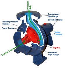
Pump Design
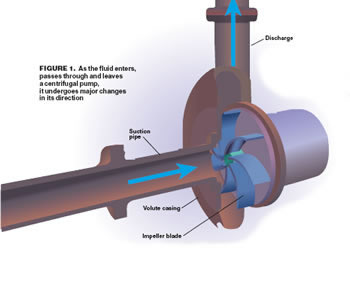
Pumps are designed to move water throughout a piping system. The cross section of the pump above is for a centrifugal pump. You will notice that water is coming into the pump on the horizontal plane and is flowing into the impeller. The impeller is then driving the water flow upwards into the vertical pipe.
Now, not all piping is configured this way.
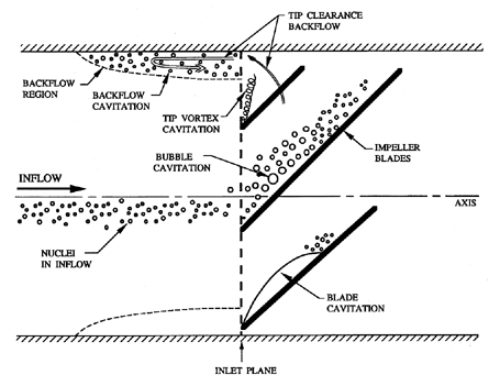
That being said, the general rule of thumb is that you need to have 5 to 10 pipe diameters in length between the inlet/outlet of the pump and the first bend. This is to account for cavitation which is visually shown below and will result in uneven distribution of water and the build up of air bubble upon the impellers. If you're feeling frisky you can read in great detail about cavitation here.
There are various types of pumps and they have different effects on design variables, but the fact remains they exist to move water. When designing a pump, you need to understand why you are moving the water and how much you need to move.
Typically, you are moving water to transfer BTU's from one source to another.
In the case of chilled water, you are moving water throughout a system to absorb BTU's from another device an example of this would be taking the heat out of an air stream via a chilled water coil. When you are selecting your pumps, you need to account for several variables.
The main variables to account for are:
- Environmental and mechanical conditions- You need to take into account if you are pumping water up a multi-story building and in which environment are your pumps going to be running.
- GPM requirements of the equipment- For this, you need to account for the GPM of all devices that are utilizing the water.
- Heat transfer or Delta T- This will help you understand how much your flow rate needs to be in order to effectively transfer the proper BTU Load.
- Loop type- Are you using a Single loop with constant volume or are you using a Primary/Secondary loop with variable flow and mixing valves?
A great article that was published in the ASHRAE Journal about designing central plants is posted here.
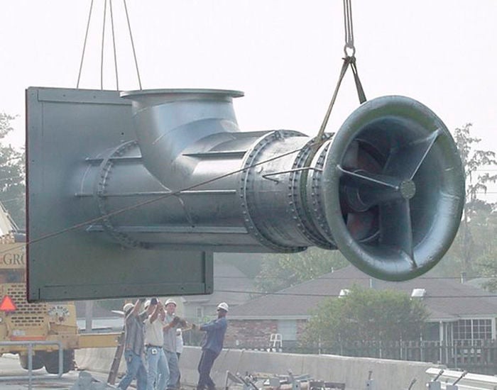
Pump Types
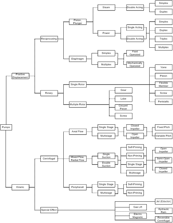
As you can imagine from the diagram above, I could literally write pages going through each type of pump. Fortunately for you, there are only three types of pumps I am going to discuss. The three types of pumps I will discuss are:
- Centrifugal Pumps
- Reciprocating Pumps
- Rotary Pumps
In order to further understand the difference between positive displacement pumps and kinetic pumps, refer to this detailed article here.
Centrifugal Pumps
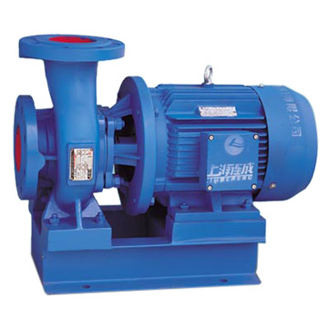
Centrifugal pumps are the big daddy of pumps (yes, that is a technical term). They have a capacity of more than 100k GPM and can be equipped with variable speed drives.
If you need to move a lot of water in a medium pressure environment, a Centrifugal pump is the pump of choice. However, you must be aware that a Centrifugal pump is limited in the pressure levels that it supports and it significantly looses efficiency when you utilize it above 1000 psi.
A centrifugal pump utilizes an impeller to pull water into the suction side of the pump. The impeller spins and literally scoops the water up and pushes it out the pressure side of the pump. The action and angle of the impeller is typically engineered for the suction side to be horizontal and the pressure side of the pump to be vertical.
Reciprocating Pumps
While the Reciprocating pump does not have the high flow rate of the centrifugal pump, it makes up for its lower flow rate by having a significantly higher pressure capacity (100k PSIG+).
When you need to move dense liquids or you need to pump against atmospheric pressure, you can utilize a reciprocating pump to overcome high-pressure scenarios. A Reciprocating pump is great for pressures above 1000 psi that require a medium to low flow rate.
Additionally, if you are going to be moving fluids such as oils or other viscous fluids, then you will want to utilize a reciprocating pump. Quite frankly, I can count on one hand the amount of reciprocating pumps I have seen in chiller plants.
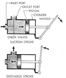
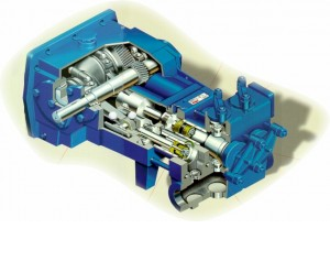
The mechanics of a reciprocating pump are quite simple. The pump utilizes a piston that is driven forward inside the pump's cylinder by a motor. The action of retracting the piston pulls liquid in the inlet and the contraction of the piston pushes the liquid out the outlet port. The lack of complex parts allows the reciprocating pump to be utilized for many corrosive liquids.
Rotary Pumps
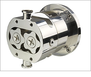
The rotary pump has a low flow rate and does pump water at high-pressure rates.
The rotary pump makes up for these capabilities gaps by being a highly efficient pump when it comes to thick liquids. When you need to move thick liquids, you can rely on a rotary pump to provide optimal performance. While not very common in central plants, you will see rotary pumps in process control and in some treatment facilities on processed water.
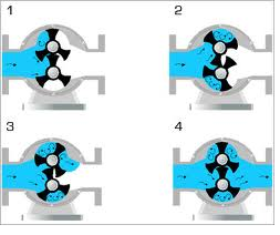
A rotary pump or a rotary vane pump functions like most positive displacement pumps in that it displaces water on the supply side. Unlike a Reciprocating pump, which utilizes a piston, a rotary pump utilizes vanes that trap the water between the two vanes and move the water from the inlet side of the pump to the outlet side of the pump. These pumps are often utilized in situations that require a pump to handle highly viscous fluids that do not high pressure and flow requirements.
Finally, we come to the topic of condensing systems. You will often hear folks refer to the condenser side of the chiller and I don't know about you, but during the beginning of my career when I used to hear that term I got rather confused.
So, let's wipe out that confusion once and for all. Let's dig into condensing systems!
Condensing Systems 101
You may remember that earlier in the article I told you that the heat absorbed on the evaporator side of the loop must be transferred and ultimately exhausted on the condensing side of the loop. This is accomplished through the use of condensing systems.
While not specific to central cooling plants, condensing systems are most commonly found in central plants. These condensing systems are typically called Cooling Towers and Condenser Water Loops. This section will explain to you the basic design and function of these loops, multiple methods and theories around cooling tower design, and the dynamics that indicate cooling tower failure.
The Refrigeration Cycle
Way Back When.....
I still remember meeting with the mechanical contractor on a Hot 100+ Degree summer day in Dallas Texas.
According to the contractor, we had entered the wrong pressure setpoint on the condenser loop, and this was causing the pump to break its seals, causing water to spray all over the mechanical room. Well after hours of adjusting setpoints the issue continued. I pointed out that maybe, just maybe there might be an issue with how the condenser loop was designed.
Soo...
We went out and traced the loop.
Sure enough, there was a three-way bypass valve that was supposed to bypass the open cell cooling towers (more on this later). However, the pipe-fitter had neglected to pipe the flow over the tower and rather had the pipe simply draining the tower when the loop was at full bypass.
Well, long story short this was causing a vortex in the tower and was creating a giant air bubble in the loop.
Therefore whenever the bypass valve opened and water began to flow the air bubble would have nowhere to go and would cause the pump to expel water. That was a long day of tracing pipe and arguing with a mechanical contractor, but it illustrates the reality of why BAS professionals need to understand condenser loops.
Condenser loop types
Condensing systems and more specifically cooling towers are used with water-cooled chillers, plate frame heat exchangers, and water-cooled DX Units. The purpose of the condenser loop is to extract heat from a cooling loop and to transfer that heat to another medium (water, air, ground, etc. ).
There are typically three main types of condenser loop systems:
- Cooling towers
- DX Loops
- Heat Exchangers
In this section, I will be discussing Cooling Towers as I have discussed DX loops and heat-exchangers earlier in the article.
To Fan or not to Fan that is a Question
Cooling towers rely on airflow to transfer heat out of the condenser water and into the air stream. There are three main methods of Air Flow:
- Natural Flow
- Forced Draft
- Induced Draft
Natural Flow
People Say I've Got a Natural Flow
Natural flow is not used as the primary method of airflow design in most commercial or industrial buildings. You mainly see natural flow being used in power plants or systems that have large stacks that let heat naturally rise and transfer inside a tall exhaust stack. This is the method you need to be least concerned about.
Forced Draft-
I can be rather forceful
Forced and Induced Draft seem similar at first glance but don't worry there is an easy way to remember the differences in the two systems.
When you force someone through a door, you are pushing them through the doorway. Forced draft works by putting a fan at the intake of the cooling tower and effectively pushing the air through the tower. Now the happy little air particles can dance around and do the BTU shuffle inside the cooling tower as they transfer BTU's from warm condenser water to the outside air via evaporation.
In Judo it takes more energy to push someone than it takes to pull them and use their momentum. Because of this Forced draft systems usually need to be designed with larger fans that are capable of higher horsepower. The con of this is that your fans need to be bigger, while the pro is that because of the larger fans you can have your tower installed in confined spaces that require higher pressure draws due to the smaller air volume!
Induced Draft-
People say I suck
Going back to our door analogy-induced draft systems pull airflow through the tower. The induced draft takes advantage of pressure and temperature laws to allow the airflow to work for the fan rather than against it.
The Induced draft tower is the reverse of the Forced draft tower.
If the Forced draft tower is trying to push the fat guy through the door, the induced draft tower is waving a doughnut in front of him and giving him a gentle pull using the force of his 400 lb frame to get him to come inside. Induced draft towers can have smaller fans but require greater volumes of air.
If the guy coming in the door is an 80lb stick figure, then the induced draft fan have to work a lot harder because of the lack of momentum.
What to Do With a Draft
Let's confuse you a little more: A+B=C unless B+C=A or D or E....
So your system has a natural flow or mechanically induced draft, that's great. What do you do with this draft?
Why do you need it?
Well if you've ever studied my friend the psychometric chart, then you would know that, as you add cool moisture to dry, warm air, the water cools the air because the BTU's are leaving the water and "saturating" the air.
If we get rid of BTU's, we are getting rid of heat!
Less heat equals cooler water.
Thus we have two main ways of getting the air to absorb the heat from the return water.
Let it RAIN!
When we let the water rain down "over the top" of the tower, we are creating a stream of water that the air will flow through. Sometimes this looks like water running down rivets on the inside of the tower. Other times this looks like the water simply dripping into the tower basin (bottom).
Push that water Through
If you push water through the basin of the tower and then use fans to force a draft of air over the surface of the water, then the BTUs in the water will be absorbed by the air. While not as efficient as making it rain, this still will provide some BTU transfer.
Most designs use "through the tower" instead of "over the tower" when there is a low load condition.
Operating the Tower - More Design Fun!
Oh, you use your cooling tower to water your parking lot, that's smart ...
In addition to airflow design, cooling towers consist of a single or multi-cell structure with a common or isolated sump.
The easiest way to think of a multi-cell tower is to think of a multi-chiller plant. If you have variable loads, you want to be able to use the least amount of chillers to reach 42 degrees as possible. If I have a single 2,000-ton chiller and my load is 200 tons then I will be cycling that chiller like crazy (think turning on and off the chiller rapidly).
If your tower has to maintain 85-degree condenser water and it is sized for a 2,000-ton load, you will be ramping the tower fan, pumps, and bypass valve like crazy.
Or.... you could simply split your tower into multiple cells and divide the load into smaller towers.
The operation of the tower during a normal cooling season OAT>68 degrees is as follows.
- Upon initiation of the cooling system. The cooling tower will control to 85 degrees supply water (adj).
- The cooling tower will initially open the cooling tower bypass valve to control temperature or head pressure.
- Then once the valve is 80% open, and the setpoint is still not reached the fans will begin to ramp up with a minimum speed of 30%.
- Upon reaching 80% (adj) the cooling tower, if it is multi-cell, will begin to ramp up the second fan and the two fans will then track to the same fan speed in order to control to 85-degree adj.
- Reverse the sequence to stage down
Depending on your refrigeration and chiller design colder water can be more efficient due to being able to absorb more BTU's and provide a more efficient heat transfer. The typical setpoint is 85 degrees adjustable, but some chillers are now accepting 55-degree condenser water setpoints.
The key point of the sequence above is that first we introduce flow to the tower WHEN WE ARE ABOVE THE OAT ENABLE SETPOINT (don't want to freeze any pipe, well unless you are in the disaster cleanup business).
0as the return water at the chiller heats up we begin to ramp up the fan speed. Now if you have a constant volume fan or do not have a bypass valve, then you simply turn on the pump initially and if the temperature continues to rise you will turn on the cooling tower fan. Typically a sequence block with a minimum-on-time but no minimum-off-time is acceptable for controlling the tower.
Conclusion
There you have it.
A crash course in chilled water systems. It is vitally important that you understand this information.
Now that you understand this information you are ready to dive into a slightly less complex topic, airside systems. And I will cover that in my next HVAC article.
By the way, if you are ready to take your knowledge of Building Automation Systems to the next level then I encourage you to learn more about my new book BAS A to Z by clicking here.